Need help with a SA300

Rich,
Quick question.
When you separated your bias adjustments, did you just replicate the design of the power supply after the rectifier/diode and then connect each individually to the DC balance pot? I am ordering parts. I will look for your past post on the subject.
Thanks,
Curt
 
Yup, I spent a while carefully reading that thread , and I think I know what to do. Ordering parts, fingers crossed.
 
Thanks, My plan is to do, in this order:
Replace cathode resistors and see if I can get it to bias within spec.
Replace the selenium rectifier. There is a few volts drop across it. This should help with the biasing problem also.
Split the bias supplies. I think I will drill 2 new holes in the plate and mount the pots on either side and a little lower( higher if looking from below) of the existing location. I think there is room.
Install in rush current limiters. I have CL60's on order.
install 100 ohm 1/4 watt screen stability resistors.
 
Split the bias supplies. I think I will drill 2 new holes in the plate and mount the pots on either side and a little lower( higher if looking from below) of the existing location. I think there is room.

Be careful when you remove the plate. I de-soldered the wires to the hum pots. Make sure their terminals don't short against the wall when you put it back together. There's no insulation and it's easy to push them back and cause a short.
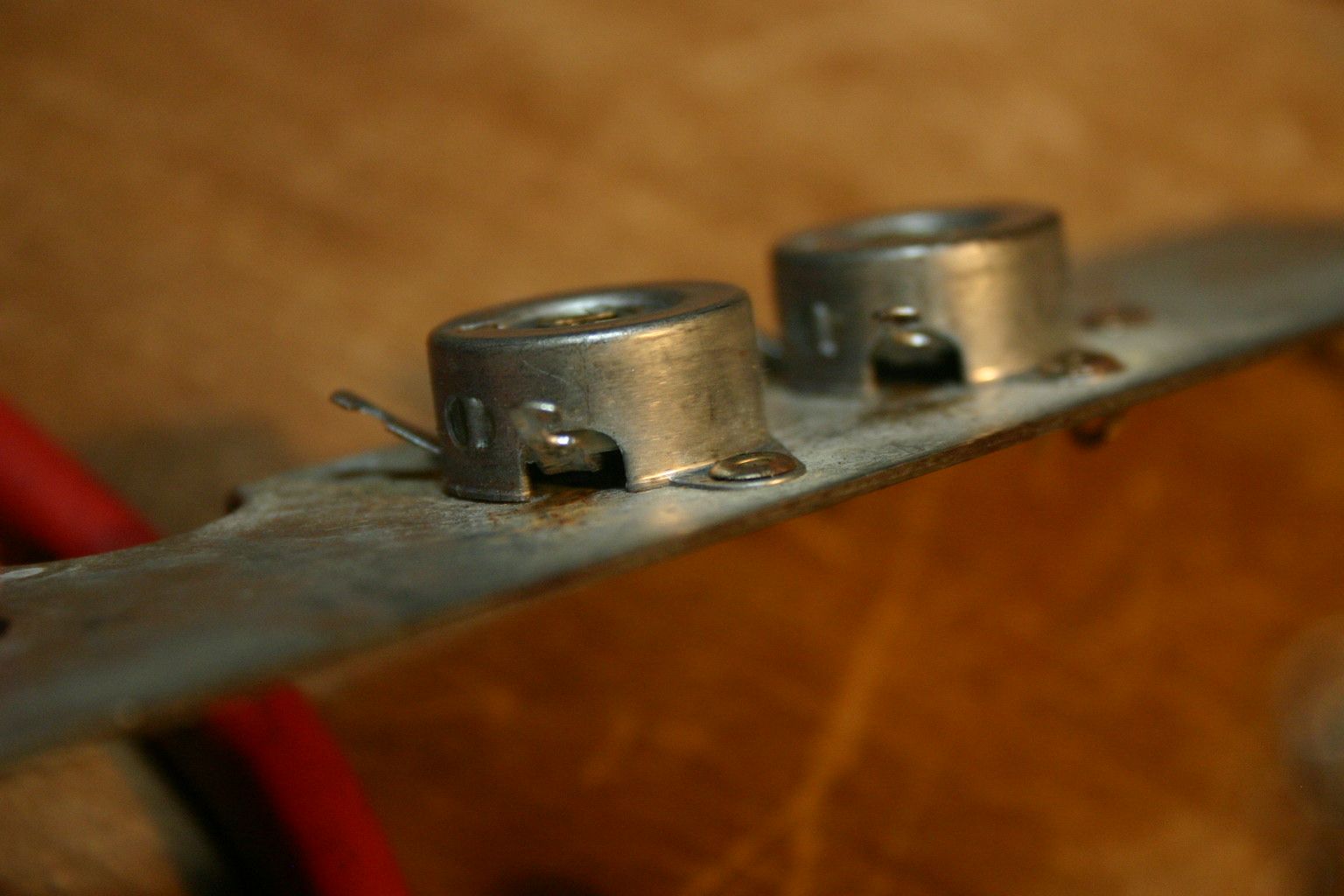
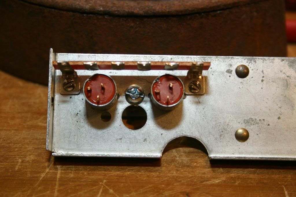
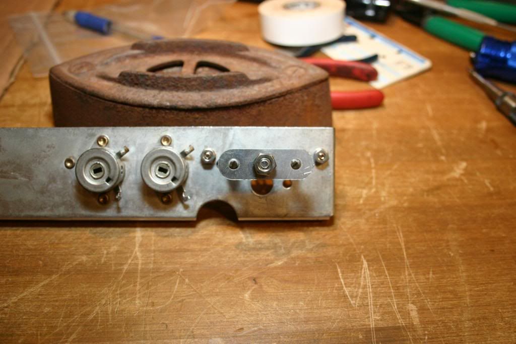
IMG_4180_zpssyhrd0yl.jpg


IMG_4206_zps0f6155c4.jpg


IMG_4202_zps02d03dcc.jpg
 
The only thing that will cause the output tubes of the two channels to give different indications is the a mismatch of the 50 ohm resistors, and the output tubes themselves. The fifty ohm resistors should be good quality 5 watt devices. If need be, for a tight match between them, the one with the highest value can be trimmed down to match the one with a lower value.

If you bridge the existing selenium rectifier with a silicon one and the voltage at its output goes up notably, then it should definitely be replaced. If it doesn't, then replace it at your own option.

Dave
OK I finally received some replacement parts. Out of the stuff I found a pair of 50 ohm 5W cathode resistors that both measured 48.5 ohms. I installed them and replaced the 15k ohm resistor in the bias power supply circuit. With the bias pot full clockwise I now have 7.8 vdc and 8.8 vdc measured at each pair of tubes. I was hoping for equal readings. Swapping tube pairs has no affect on readings. Any ideas?
 
Not really sure why at full clockwise you're getting 7.8vdc and 8.8vdc, but it really shouldn't matter because both supplies come from the same source (diode).
Therefore, if you back off one control (8.8vdc), the other channel should rise.
Set each side for 7.8vdc at pin 8 of each side and you should be gold.
In addition to replacing the 50ohm cathode resistors, I also replaced the two 150uf bypass caps (using 75u+75uf per channel).
 
Rich,
I also replaced the 150 uf bypass caps earlier. I have not separated the bias yet, so I cannot set it individually. I am also concerned at full clockwise I read .6 ohms at the pot lugs. The new pots that I have that I plan to use to separate the bias controls read 3 ohms full clockwise. that will make my voltages even higher.
 
Yeah -- my bad, and a big one. I haven't really worked with the 300 that much, so this point -- relative to your concern -- just got missed in my original quick glance at the schematic.

The 300 is a partially direct coupled design. Therefore, even with matched output tube cathode resistors, and matched output tubes, the particular characteristics of the driver tube and AF Amplifier tube will affect the output tube bias levels. Therefore:

1. First, swap the 12AU7s and see if that doesn't swap the bias problem. But also --

2. Because the 12AU7 is direct coupled from the 12AX7 AF amplifier stage, also swap these two tubes as well if #1 doesn't correct the issue.

If there are significant characteristic differences in either of these tubes between the two channels, it will ultimately affect the bias reading of the individual output stages, regardless of how matched the output tubes, and their relative components are.

Sorry for the confusion of my previous post. I hope this helps!

Dave
 
With the bias pot full clockwise I now have 7.8 vdc and 8.8 vdc measured at each pair of tubes.
Not really sure why at full clockwise you're getting 7.8vdc and 8.8vdc, but it really shouldn't matter because both supplies come from the same source (diode).

Sorry. My last post was based on the assumption that you had already split the bias supply.
After reading Dave's explanation, splitting the bias supply makes even more sense to me now.

PS-Dave-
If one of these SA300's ever crosses your path, I think you might enjoy it. Since I replaced the 12AU7's with 5814's, the SA300 has become my favorite amp. I think it's every bit as clear and accurate as my SA100 only more "musical".
Maybe I just got lucky with this one, but I think replacing the 12AU7's with 5814's made a huge difference.
 
Hey -- I recently got one -- and a fairly nice one at that. I just haven't had any time to do anything with it but confirm that it does work. I do plan to get into it later in the coming year......

Dave
 
I recently got one -- and a fairly nice one at that. I just haven't had any time to do anything with it but confirm that it does work. I do plan to get into it later in the coming year......

I feel like I just found out that one of my favorite recording artists went back into the studio!
I enjoy the way you examine, analyze and write and can't wait to read all about it.
 
Yeah -- my bad, and a big one. I haven't really worked with the 300 that much, so this point -- relative to your concern -- just got missed in my original quick glance at the schematic.

The 300 is a partially direct coupled design. Therefore, even with matched output tube cathode resistors, and matched output tubes, the particular characteristics of the driver tube and AF Amplifier tube will affect the output tube bias levels. Therefore:

1. First, swap the 12AU7s and see if that doesn't swap the bias problem. But also --

2. Because the 12AU7 is direct coupled from the 12AX7 AF amplifier stage, also swap these two tubes as well if #1 doesn't correct the issue.

If there are significant characteristic differences in either of these tubes between the two channels, it will ultimately affect the bias reading of the individual output stages, regardless of how matched the output tubes, and their relative components are.

Sorry for the confusion of my previous post. I hope this helps!

Dave

I swapped the 12AU7s and then the 12AX7AFs. The bias problem did not swap. I was hoping that was it.
 
I swapped the 12AU7s and then the 12AX7AFs. The bias problem did not swap. I was hoping that was it.

I think all you can do at this point is go thru the amp and compare voltage readings point by point channel against channel. Hopefully it's something simple like a power supply problem.
I would suggest investing in some "grabber" type probes so you don't slip and cause a short.
BTW-have you checked the AC/DC balance and hum pots? Are they correctly set? If you look at Fisher's instructions, hum and balance are checked first. Bias is the last item on the procedure list.
 
I did check the tube voltages as described in the service manual . The output tubes are in spec and very close. The 12AU7 read a little high at Pin 1 and 6.
I had the balance and hum pot set the best I could with the Fluke. I did tweak them some while watching the bias voltage and they seemed to have no effect.
I guess I will start checking voltages elsewhere.
 
Hey -- I recently got one -- and a fairly nice one at that. I just haven't had any time to do anything with it but confirm that it does work. I do plan to get into it later in the coming year......

Dave

Very cool. Like Rich, as an owner of one of these amps, I am looking forward to your analysis of the SA300.

If I had one complaint about these amps, or at least the one I own, it would be grounding issues. The rivets being a different metal then the chassis doesn't help with them making the mechanical connection. I abandoned trying to solder to the chassis, I was successful in one location but it was very difficult.. The addition of internal tooth washers with a nut and bolt in several strategic locations where there were rivets definitely helped, as well as a few wires connecting the grounds. Although, Curt sounds lucky because his amp is nice and quiet.
 
Last edited:
Curt -- The next things to check would be the resistor values that make up the DC balance control circuits, the output tube grid return resistors, the driver stage plate load resistors, and AC balance control etc. If these components vary considerably with their counterpart between the channels, it will also cause the output tubes to bias differently as well. At some point, I am sure you will track the difference down.

Dave


One year later and I am back at it. I have separated the bias supplies as shown in the attached schematic. I read where Dave said to increase the 15k resistors to 33k which I have not done. The supplies seem to be interacting with each other. Is that all I need to do,change 15k to 33k, or have I made a mistake? Note that I also took Dave's advice and used 10,k pots
There was enough room to drill the existing metal plate to the left of the existing pot and use that location for the second pot. Photos to follow.
 

Attachments

  • IMG_5632[1].JPG
    IMG_5632[1].JPG
    35.9 KB · Views: 16
Back
Top Bottom