

qboneus
Senior Member
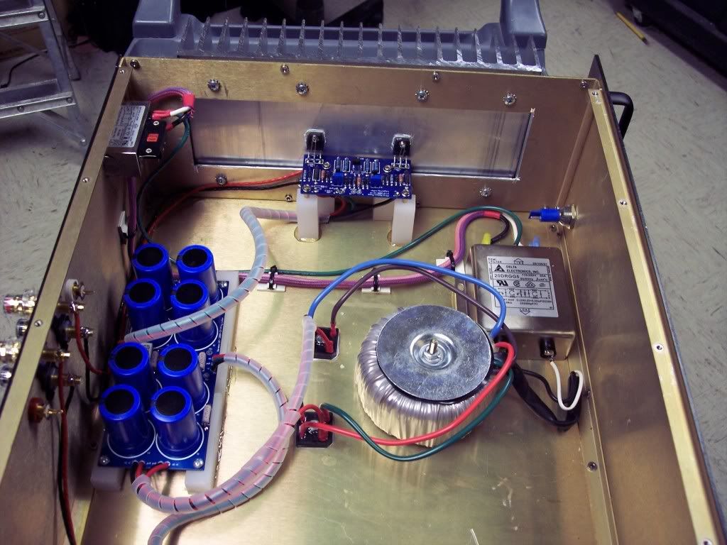
Inspired by Jeff's F5 thread I had to start my own project.
Rather than crap his thread i am posting a different build of the same amplifier using some different components.
I started with MMmetals heatsinks 6.5"x12.25"x2.3"
(SurfaceArea sq"/1") 96.972
www.mmmetals.com/extrusions/drawings/MK62430.JPG
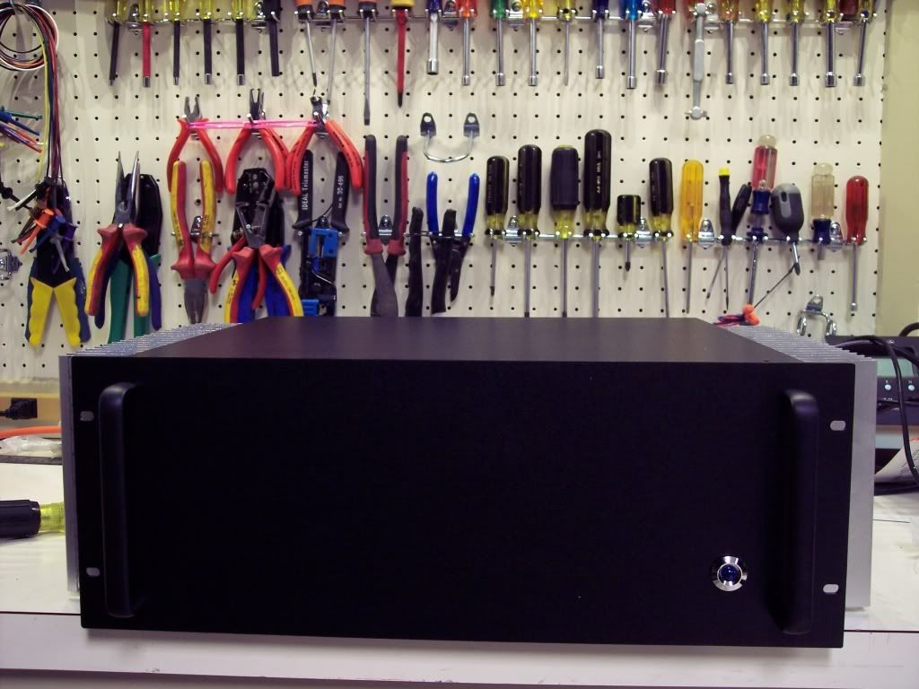
Par-metals EMI/RF shielded enclosure.
http://www.par-metal.com/14series.htm
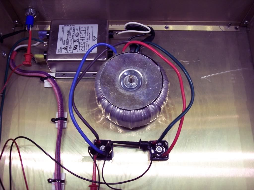
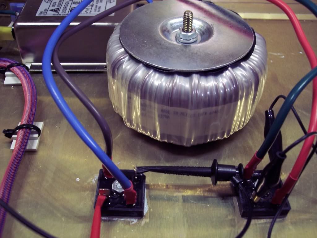
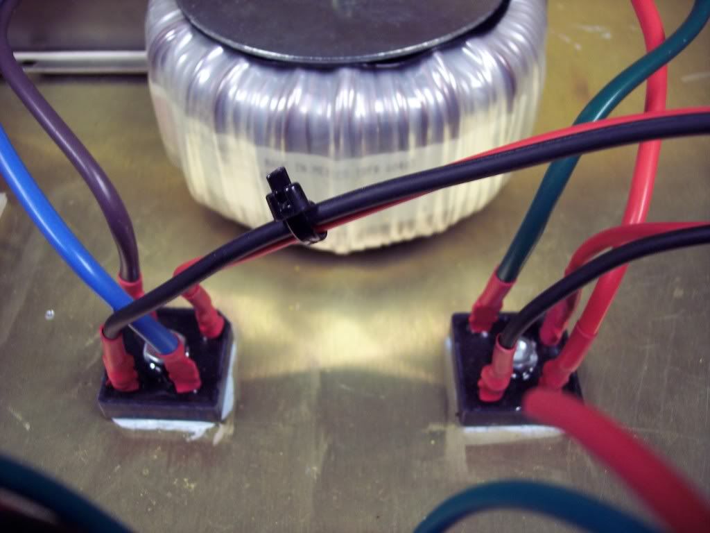
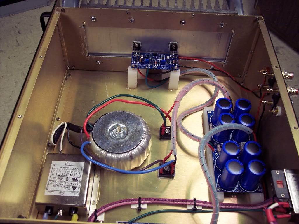
Acme/Amveco 400Va 18Vx2 audio grade power transformer.
http://search.digikey.com/scripts/DkSearch/dksus.dll?lang=en&site=US&KeyWords=TE60403-ND&x=17&y=11
WBT Binding posts
http://www.wbtusa.com/pages/0765m.html
and RCA's
http://www.wbtusa.com/pages/0201t.html
I sourced the Semiconductors at
http://www.tech-diy.com/Store/CloneKits.htm
power entry module.
http://search.digikey.com/scripts/D..._link=hp_go_button&KeyWords=Q305-ND&x=25&y=13
24V 19mm indicator.
http://search.digikey.com/scripts/DkSearch/dksus.dll?Detail&name=679-1745-ND
High performance entry power filter.
http://search.digikey.com/scripts/DkSearch/dksus.dll?lang=en&site=US&KeyWords=603-1147-ND
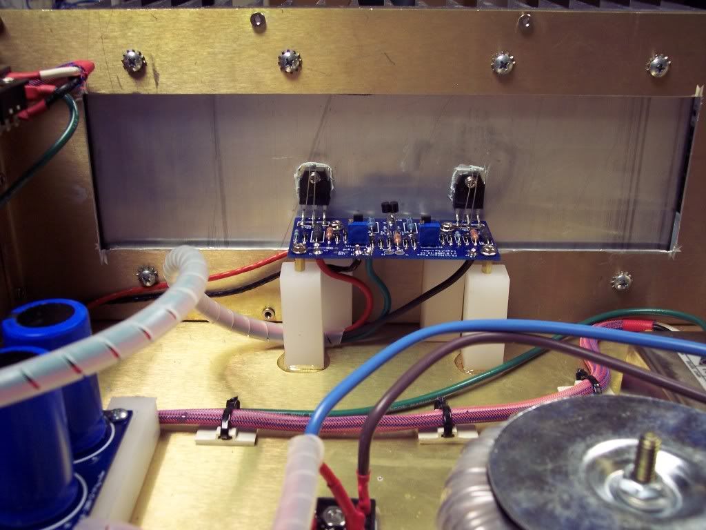
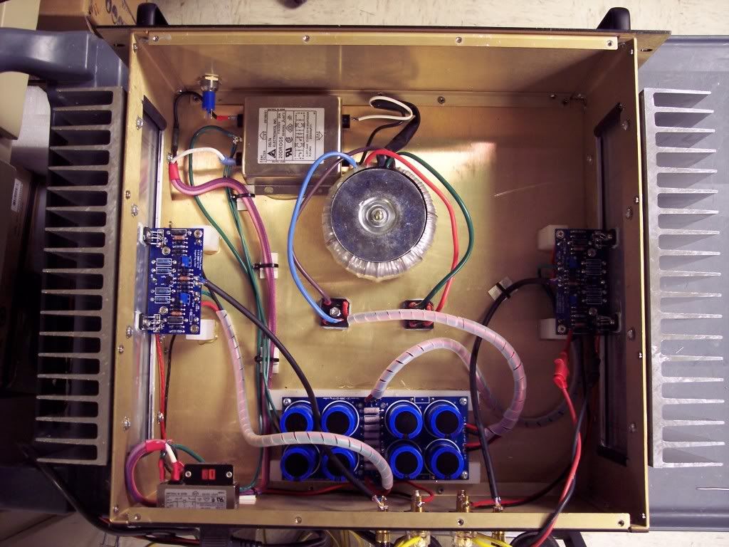
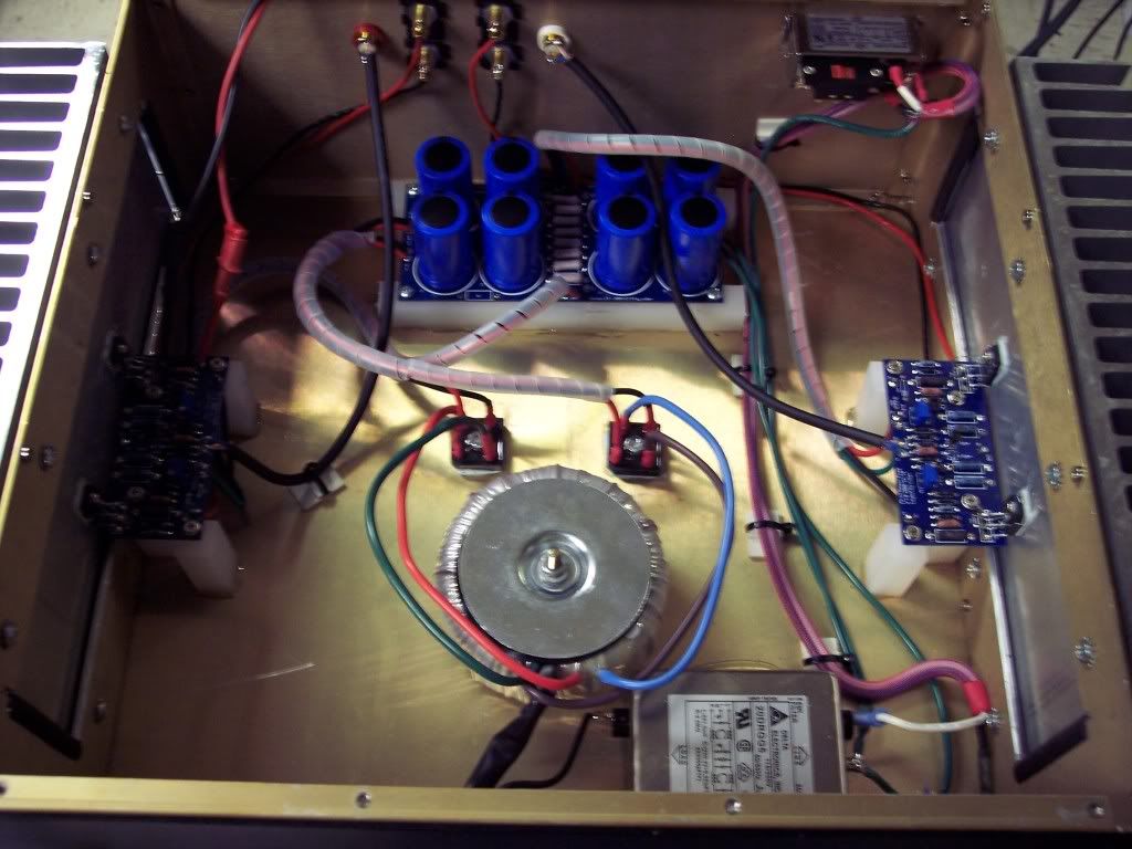
enough of the starting details here's a few build pictures!
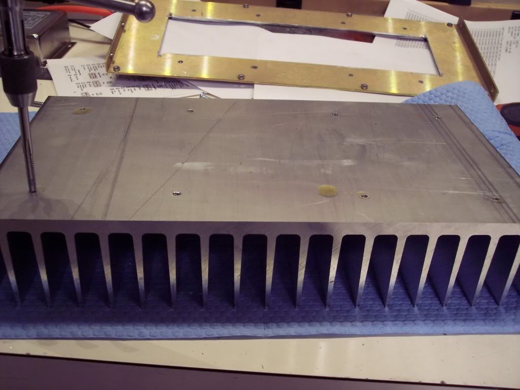
Here I am tapping the heatsinks out to a 10-24 N.C threading.
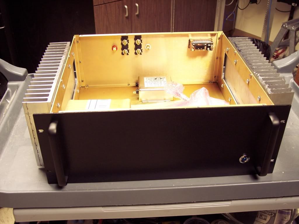
i had to cut out the side panels and build stand-offs to place the heatsinks away from the top edge of the sides so that the top can be placed on.
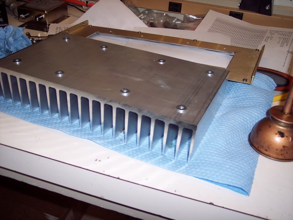
then I mounted the heatsinks to the side of the enclosure utilizing 8 10-24 1/2" fasteners per heatsink.
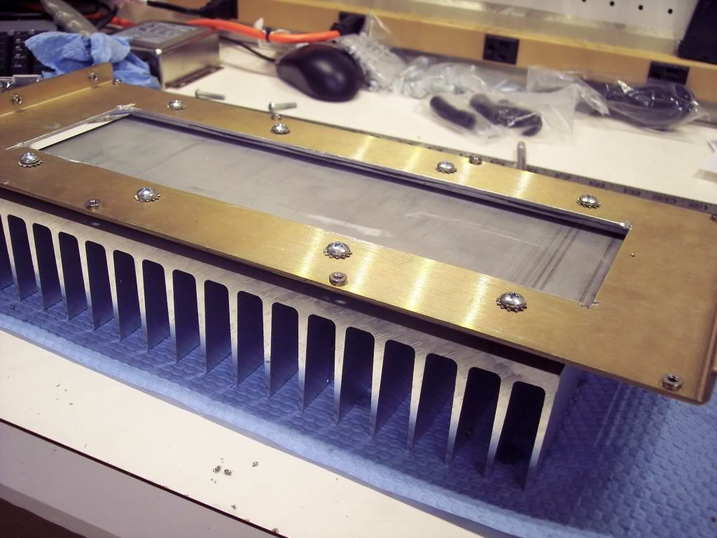
i cut the openings a little over on the edges of the hs on the sides to try and improve circulation and mounted the heatsinks to the enclosure
I am going to need to cut some ventilation into the top as well.
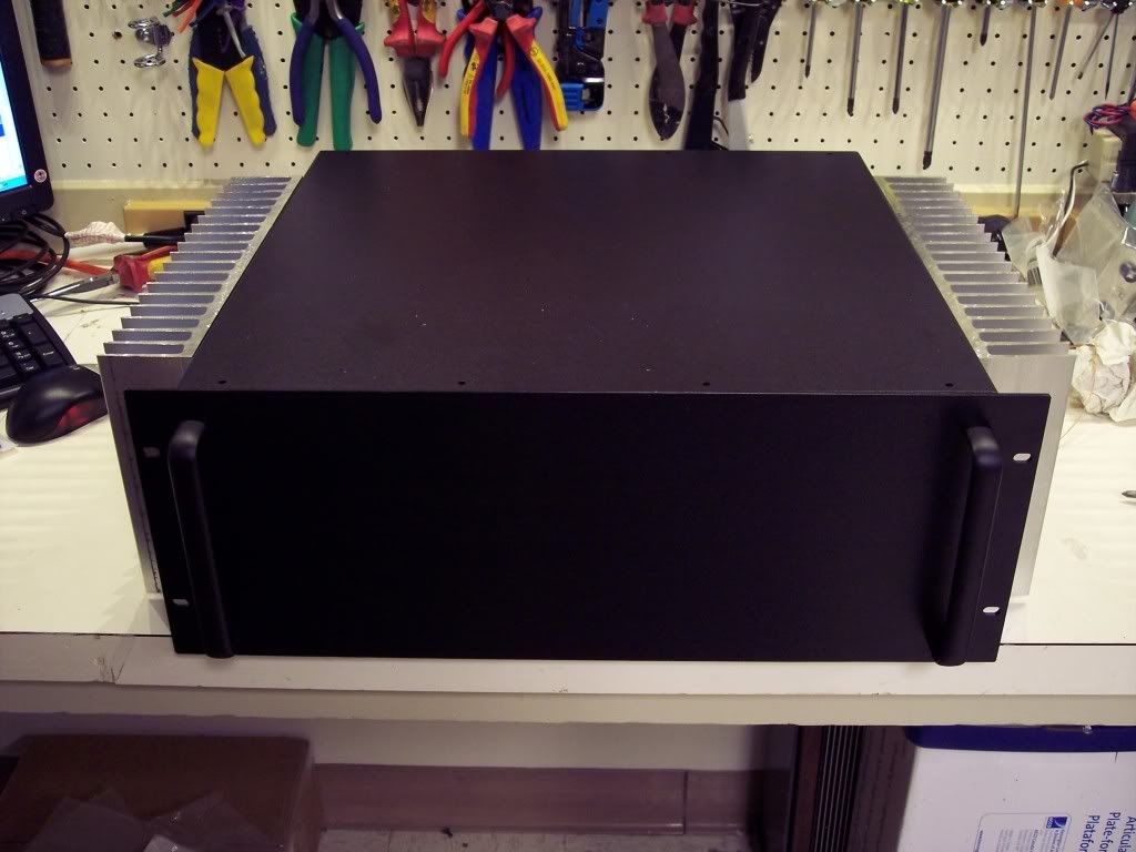
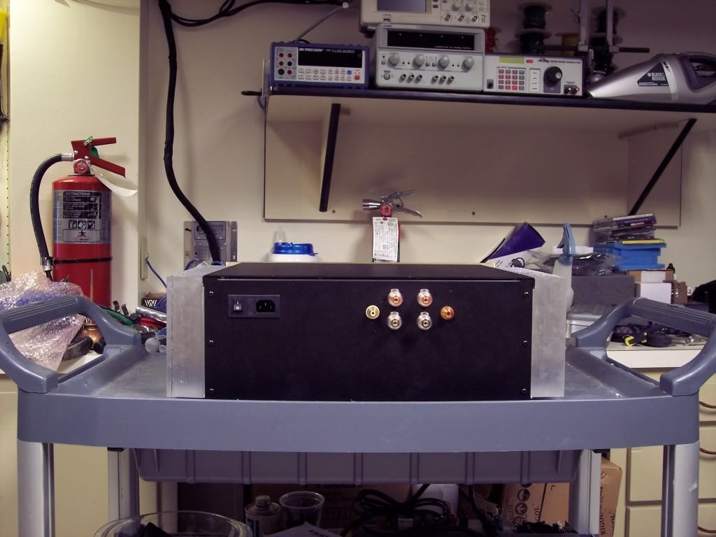
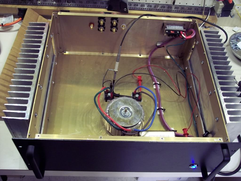
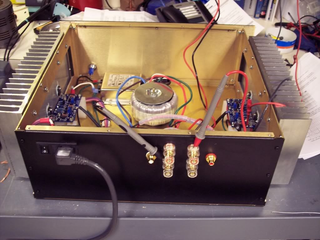
Next I cut in the Binding posts, RCA's and power entry module

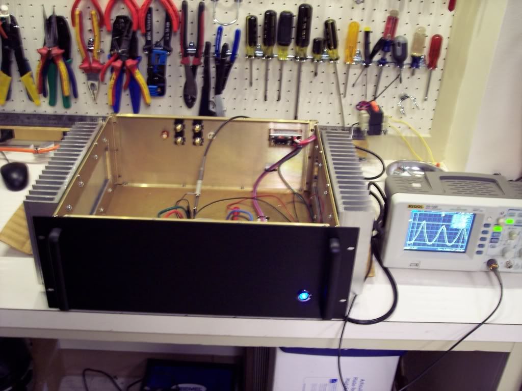
followed by my 19mm indicator light.
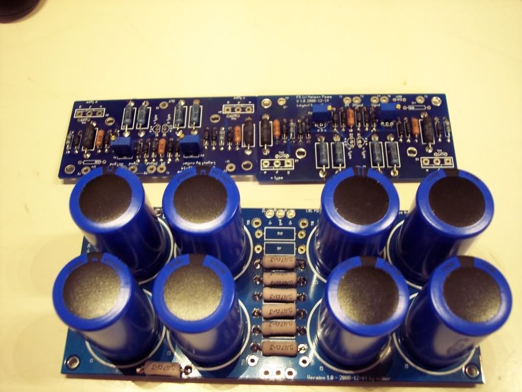
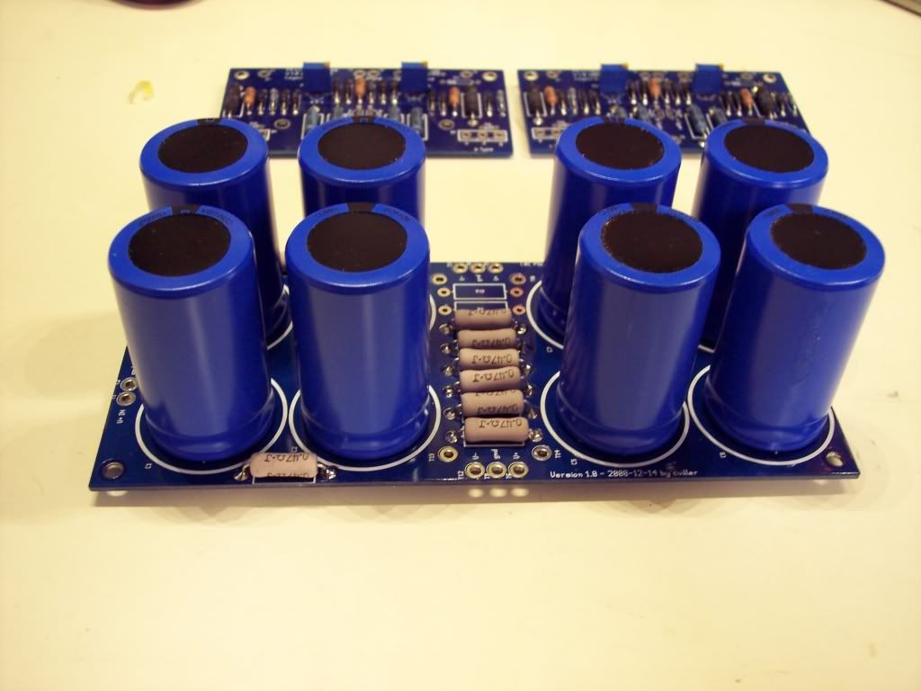
I have everything else needed and a few upgrades :yes:already standing by, but I am awaiting my PCB's to be able to proceed any further..
hopefully they should arrive here from Canada on monday..
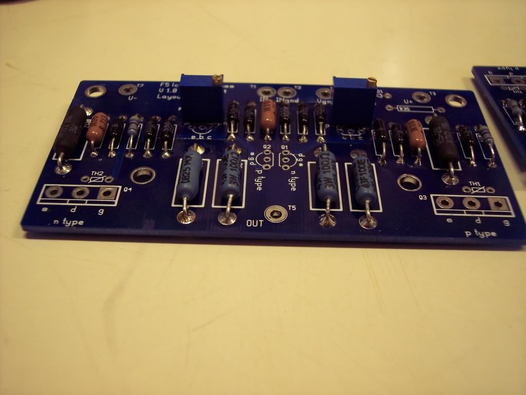
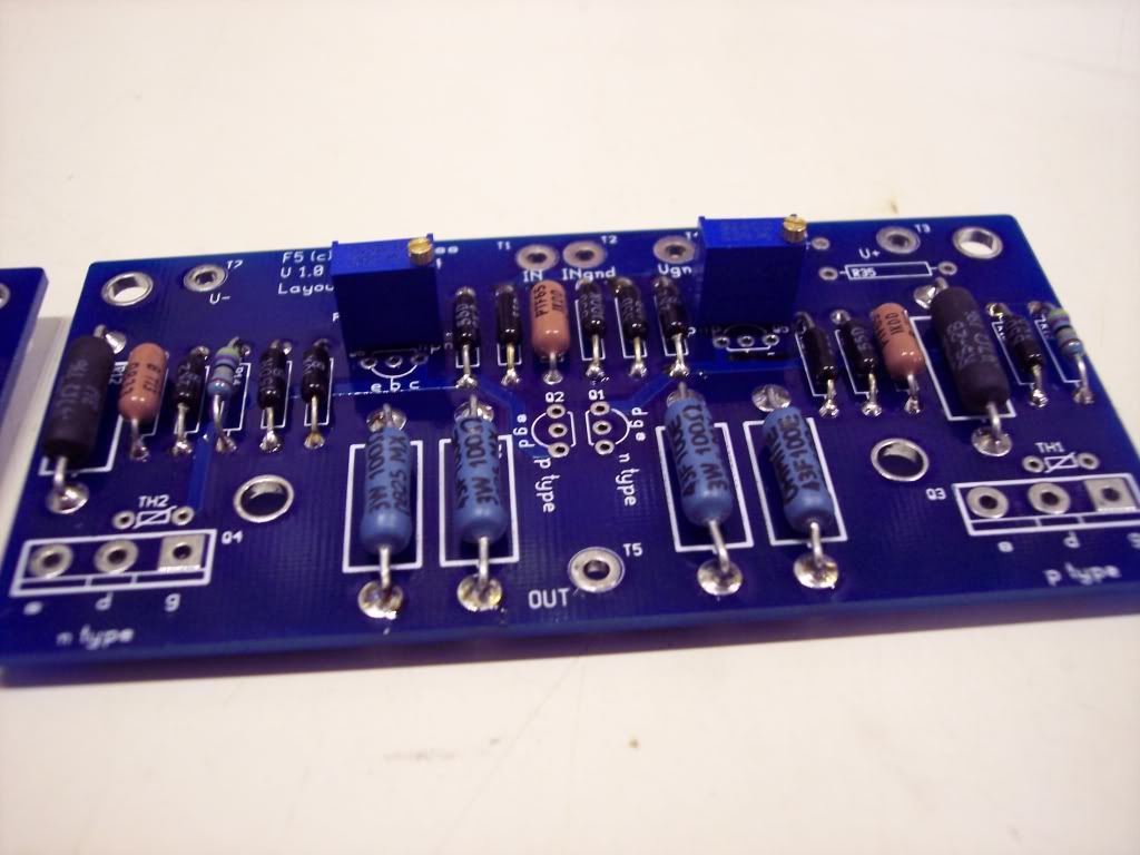
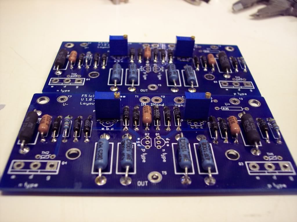
Resistors are IRC .1% precision resistors with exception of a few 'select' positions that I decided to upgrade to better resistors yet..
more to follow shortly.
tal
Rather than crap his thread i am posting a different build of the same amplifier using some different components.
I started with MMmetals heatsinks 6.5"x12.25"x2.3"
(SurfaceArea sq"/1") 96.972
www.mmmetals.com/extrusions/drawings/MK62430.JPG
Par-metals EMI/RF shielded enclosure.
http://www.par-metal.com/14series.htm
Acme/Amveco 400Va 18Vx2 audio grade power transformer.
http://search.digikey.com/scripts/DkSearch/dksus.dll?lang=en&site=US&KeyWords=TE60403-ND&x=17&y=11
WBT Binding posts
http://www.wbtusa.com/pages/0765m.html
and RCA's
http://www.wbtusa.com/pages/0201t.html
I sourced the Semiconductors at
http://www.tech-diy.com/Store/CloneKits.htm
power entry module.
http://search.digikey.com/scripts/D..._link=hp_go_button&KeyWords=Q305-ND&x=25&y=13
24V 19mm indicator.
http://search.digikey.com/scripts/DkSearch/dksus.dll?Detail&name=679-1745-ND
High performance entry power filter.
http://search.digikey.com/scripts/DkSearch/dksus.dll?lang=en&site=US&KeyWords=603-1147-ND
enough of the starting details here's a few build pictures!
Here I am tapping the heatsinks out to a 10-24 N.C threading.
i had to cut out the side panels and build stand-offs to place the heatsinks away from the top edge of the sides so that the top can be placed on.
then I mounted the heatsinks to the side of the enclosure utilizing 8 10-24 1/2" fasteners per heatsink.
i cut the openings a little over on the edges of the hs on the sides to try and improve circulation and mounted the heatsinks to the enclosure
I am going to need to cut some ventilation into the top as well.
Next I cut in the Binding posts, RCA's and power entry module
followed by my 19mm indicator light.
I have everything else needed and a few upgrades :yes:already standing by, but I am awaiting my PCB's to be able to proceed any further..
hopefully they should arrive here from Canada on monday..
Resistors are IRC .1% precision resistors with exception of a few 'select' positions that I decided to upgrade to better resistors yet..
more to follow shortly.
tal


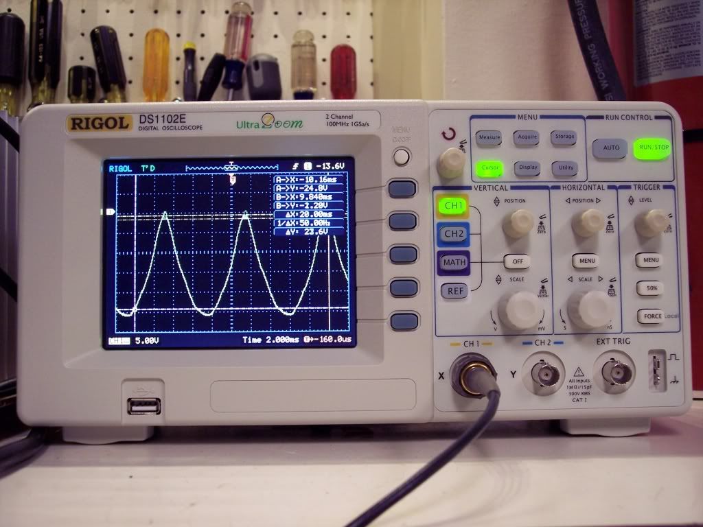
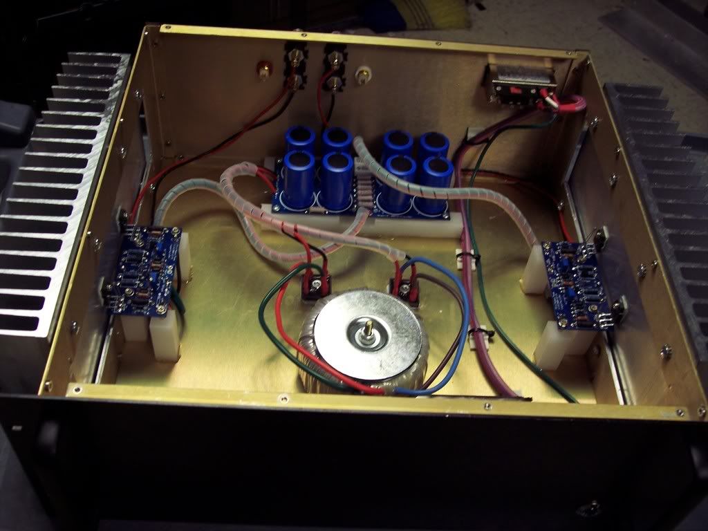
 but it is really sweet sounding:yes:


