New to Tubes...800c score...help restore.

I flat out don't think my Fisher gear sounds as good if it's not at minimum 29ma. If I had individual bias controls I'd get each tube at 31-32ma. Tubes wear out and are replaceable.....I'll use them in their design ranges. This conversation would be completely different if there wasn't a great sounding new production 7591 being made to drop right in when they eventually wear out! I try to ignore tube life and put it wherever it's safe to run for the tube and gear and sounds the best. Period.

With that being said I wouldn't listen to my recommendations, Larry's, Don's, or anyone else's as the gospel. We all have our preferences. After the new caps have ripened some, I'd start by trying to run it cold like Larry seems to be happy with first. Give it a few days and get some decent hours under your belt. Then bump it up a notch and listen. Then do it on the hot end like I like it. If you reach a point where you don't notice any increased benefits...Bingo you've got your sweet spot. :thmbsp:

I used to run mine cold being paranoid about wearing a tube out for some reason but once I tried it hot one day closer to where Avery ran it (but still cooler) I'll never go back. YMMV

Kory
 
Okay....
I've spent the morning messing around with the bias. I'll tell you that having that 10K pot at R119 makes tweeking the bias alot easier.
I'm starting to see this a bit more clearly.

Larry. I am measuring in mV and moving the decimal. The tubes are original
"The Fishers" 7591's, black base, 337/339 DP, made in USA. They tested good by my tech guy.

Kory and don, as usual your imput is welcomed and weighed.

So after a good deal of monitoring and tweeking here are the latest numbers.

120V(+-) AC Approx 5.5K on pot.
We're in the middle of a heat wave here and our house is old. So keeping a constant household voltage is iffy at best.

V10
pin 3 425
pin 4 383
pin 5 27.76
pin 6 -17.11

V11
pin 3 425
pin 4 383
pin 5 29.62
pin 6 -17.17

V13
pin 3 425
pin 4 383
pin 5 30.24
pin 6 -17.20

V14
pin 3 425
pin 4 383
pin 5 32.51
pin 6 -17.22

The numbers seem to be getting better. Perhaps it's the caps burning in. :scratch2:

I've noticed that there are trade offs in all of these target settings. Say moving closer to a -19 pin 6 setting makes my pin 5 setting colder and so on. Am I delusional?

I think individual pots for this unit are in order.

I still haven't recieved the multisection cans from hayseed. So those changes are still ahead.

I haven't changed the 330K to 200K seeing how that is part of the individual bias pot mod. More changes and descessions.

I'm thinking that a pot at R119 and individual bias pots could be a good thing. Enlighten me!

In case you guys hadn't noticed my other receint thread, my tuner section is non functional on any selector setting and my beacon light is always lit. This has happened since the metalbones portion of the restore.

thanks
martin
 
Martin, Your voltages look great. Honestly each pair of output tubes is within 2ma of each other which is matched in my book.

I have to study for my math test tomorrow though so I'll be out of commission for now. You are kickin' some butt on this thing. :thmbsp:

Kory
 
Hey Martin,

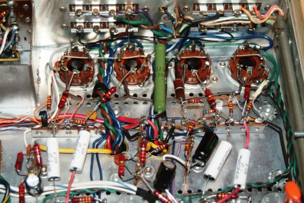
Your doing an amazing job! I had a question for you(everyone) regarding your sonicap instal. By my reading of metalbones instructions, the shielded side on the sonicaps is to the right of the printed values, or, the short leg of the cap. That shielded side is supposed to be toward the output tubes. Your picture looks like you did one side opposite that. Am I confused about how I think these should be installed? Or does it really not matter with the sonicap? I understand about positive and negitive legs, but this shielding is new to me on this project.
 
Keith...
I "think" I know where the confusion lies. See if this helps.
C16, C17, C18 & C19 are the .1uf sonicaps and nowhere in my instructions or parts bag are they labled electrolytics.
However C116 & C117 which are in the same area (on the chassis and in the instructions) are indicated as electrolytics. The instructions seem to kind of run them together.
I hope this is right... for you sake...and mine.
martin

Hmm. I know we have some different part numbers here. But my instructions say "c77 & c79 extend from pin one of v12 & v13, and the replacement caps were oriented with inner shield toward the output tubes (v8 & v10)". Basically it says that all the shielded sides should be closest to the big output tubes. I'm only referring to the sonicaps. Shielded side is closest on v8,9,10,11. At least in my documentation.
 
Last edited:
Keith...
My 800c is from the 30001-39999 series. Yours is from the 20001-29999 series. Hence the confusion. But I happen to have a copy of your schematics...original document. Why its not the one that matches my unit, I'll never know.
Anyway your right about which caps are in question, but again my instructions say nothing about orientation.
Can you type your instructions verbatim sometime. If 2 of mine are in backwards, I'd sure like to know.
martin
 
Keith...
When al else fails (actually do this first)...check the schematics. My coupling caps according to specs or anythig else...are just caps.
2:00am was way too late to try and think about all this. I don't what to think about your instructions. You can still type the instructions and share if you still need help.

martin
 
martin; those #'s are really good. If you like the sound, go for it.

No you're not going nuts or delusional, as your voltage goes down (toward ZERO)on pin 6, the mv will go up on PIN 5. And vice versa.

Think of the volt meter on your car. When it's running down the road during the day, no lights, A/C, heater, etc., it's running at about 14V. When you add a load (heater fan, lights, A/C, etc) the voltage on the gauge will drop some as the current (amps) load goes up. When you turn the accessories off the voltage comes back up as the load come off. SAME THING.

I just talked to Tom @ Hayseed. They had a batch of End Discs that were cut wrong on the laser and they had to recut them all. The factory is working hard to get the July backup caught up. I've got a Multi in that batch so it'll be another week or so.


Larry
 
Thanks Larry....nothing like a second opinion when it comes to questioning ones sanity. :D
I'm beginning to like the sound more and more. Initally the bass was lacking, but the more I run the unit under load, it seeems to be coming around. Caps burning in I suppose.

Another week or so on the multi section cans (sigh).

martin
 
Last edited:
Keith...
My 800c is from the 30001-39999 series. Yours is from the 20001-29999 series. Hence the confusion. But I happen to have a copy of your schematics...original document. Why its not the one that matches my unit, I'll never know.
Anyway your right about which caps are in question, but again my instructions say nothing about orientation.
Can you type your instructions verbatim sometime. If 2 of mine are in backwards, I'd sure like to know.
martin

Because the caps dont have a +/- value, it doesnt really make a big difference from a performance aspect. a cap is a cap. The sonicaps do however have one side shielded. metalbone does suggest putting the shielded side toward the output tubes. what I typed up before was verbatim from the instructions. "c77 & c79 extend from pin one of v12 & v13, and the replacement caps were oriented with inner shield toward the output tubes (v8 & v10)" This applied to c78 and c80 as well. I'm surprised there is nothing about it in your instructions. our units are almost identical. I guess that probably eludes to the fact that it really isnt a big deal either way. :dunno:
 
I might change mine anyway. Sheilding is to the right of lettering...right?
martin

that is what metalbone said, and on the sonicap website, I read:

"The Sonicap leads are tinned solid copper (high purity). The shorter lead is shield. Tolerance is better than 5%."

the shorter lead is to the right of the lettering on all 4 of mine.
 
Thanks Keith for being thorough.
I'll swap them around when I do the Individual Bias Pots, which might be tonight.
Good Job and thanks for the heads up.
Martin
 
Hi,
This is a thread, lots of photos and info, enjoy your fisher when you get it
done, it really feels good when you work hard on these guy's and when you turn
that switch on, and the music starts coming out of those speakers it's really great.

Tube
 
Last edited:
Tube...dude...you forgot the adjective! How am I suppose to know how you really feel without the adjectives. :D Thanks for the good word. I've been keeping a close eye on the meter as I enjoy this fisher. It seems to be getting better and better as the caps burn in. However my work bench is not in the "sweet spot". So the choice is to continue working on projects or veg on tunes.

Tonight as you can see I elected not to veg and be usefull.

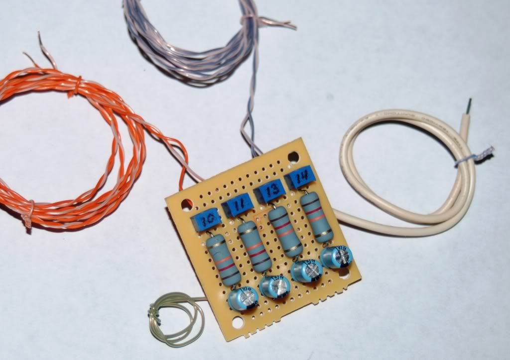
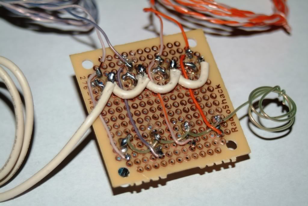
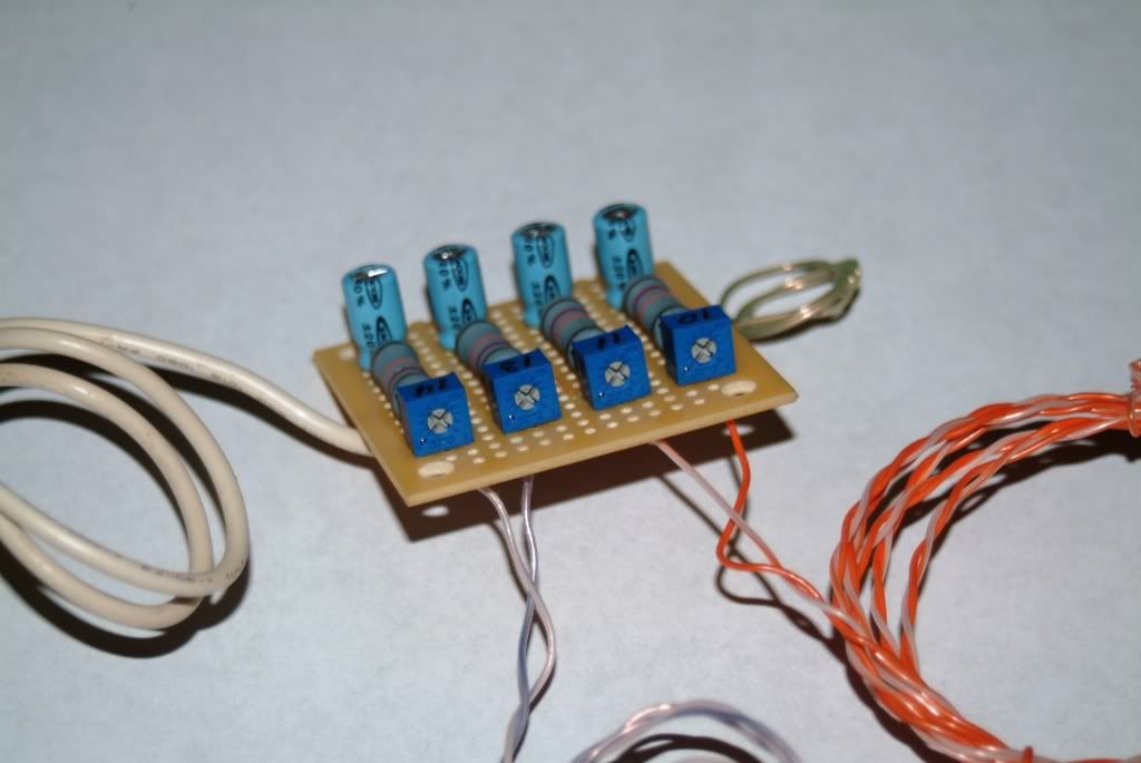
The Individual Bias Pot Mod (design by Drew Bolce) was not as easy as it could have been for two reasons.
1) It was my first and kept having to backwards engineer things. Two steps forward, one step back.
2) The small size made it impossable to use any other wire than the Cat5 plenum i had on hand(Belden 1585A for those who may want to look at the specs and inform me this is a bad idea). I will keep a close eye on it once installed.

The range numbers
V10 .01 - 6.59K
V11 .02 - 6.90K
V13 .01 - 6.40K
V14 .01 - 6.42K

So who wants to be the guinea pig and try this thing?

martin

IBPMFront.jpg


IBPMBack.jpg


IBPMTop-1.jpg
 
Martin, you and Larry have inspired me... ordered the parts to do my individual bias board.

You're doing a great job. This thread is a really good reference for anyone doing a restoration on an 800, 500 or even a 400.

BTW, when I was in the US Army many years ago went through training (Ft Jackson, SC) with a bunch of guys from Enid - nicest guys you'd ever meet!
 
Okay, It's in....

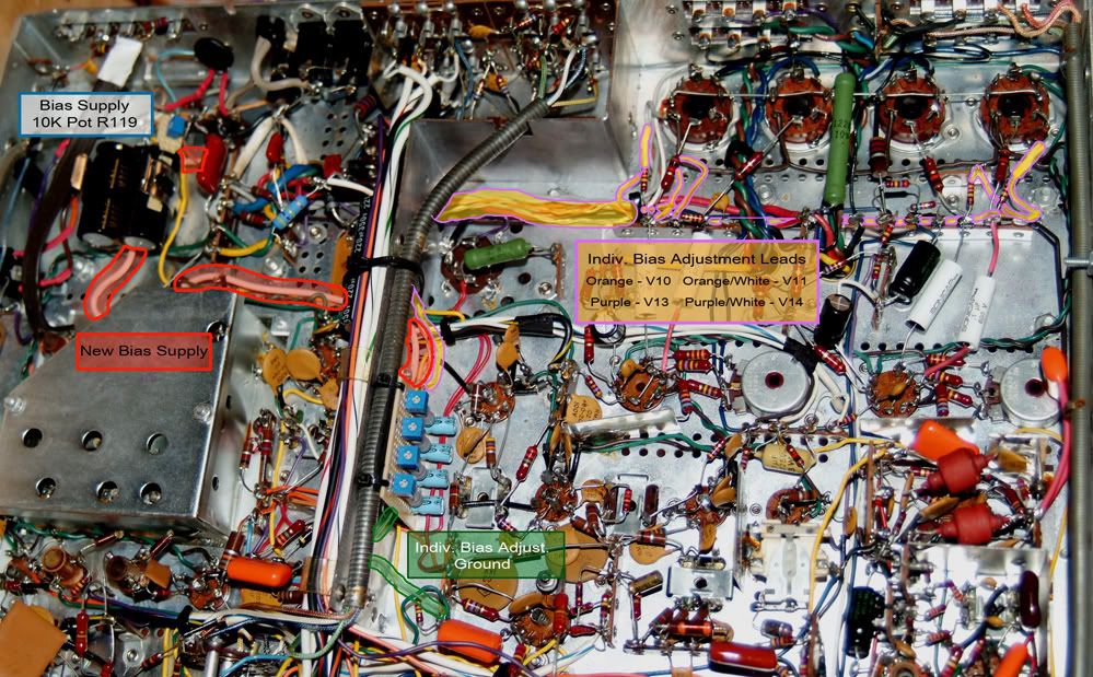
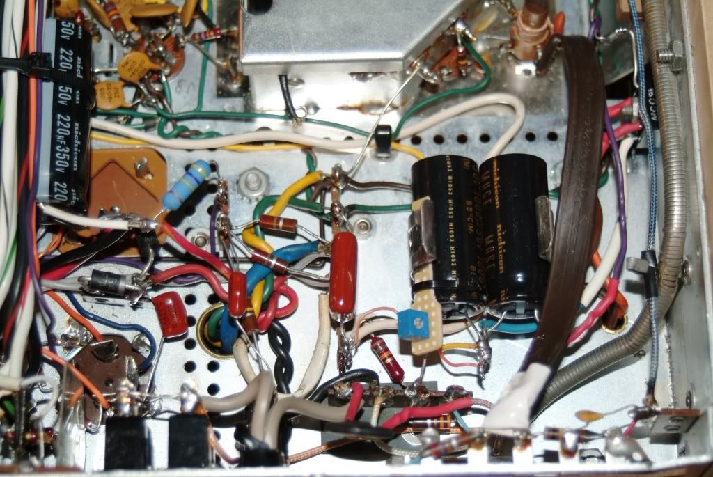
The photos are pretty self explanitory and the install fairly easy.

I reshaped the pot board at R119 just so it looked better and strapped it down for rigidity.

I took abit off the Individual Bias Adjustment Mod board because it seemed a tad tall. I used a bench grinder to do the reshaping....those boards smell like the crack when they heat up! Fair warning.

Strung new (-) bias supply wire.

Covered the connection side (back) of the Individual Bias Adjustment Mod board with 2 layers of thich rubber tape to insulate it from the chassis.

The only thing that has given me pause are the 4 - 330K ohm resistors at R21, 22, 23 and 24. Originally they were soldered together (21 & 22 / 23 & 24) on the same terminals where bias supply hooks them up.
Naturally you need to seperate them for individual biassing...at least I think so. :scratch2:

Thats about it...good luck!

IBPMinstalled3markedupflat.jpg


IBPMinstalled.jpg


IBPMinstalled4.jpg
 
Back
Top Bottom