pioneer SM-G205 recapping

Hi, I have a pristine SM-G205 tube receiver that I thought about recapping since it's 40 years old. However, it doesn't seem to contain any of the nasty old paper caps. I am wondering about the large filter cap in the canister though, it's a double cap actually. Do those go bad often? I guess if I don't hear 60 cycle hum then it's not a problem.

Any suggestions of whether to mess with this thing or just leave it be as long as it sounds ok?

Thanks,

Andrew
 
If it's that old then any electrolytic at least should be replaced just in case of near future failure.
 
Don't let those tubular, plastic covered caps under the chassis fool you, they're paper and most certianly bad by now. Japanese caps are notorious for being leaky and causing catastrophic failures.
 
Don't let those tubular, plastic covered caps under the chassis fool you, they're paper and most certianly bad by now. Japanese caps are notorious for being leaky and causing catastrophic failures.


Agree. Example: Sansui 1000A. Coupling capacitors look just like electrolytic caps and exhibit no physical signs of being bad. But they are! They will upset the bias at least and destroy the output tube/transformer at worst.

I have a 1000A. Some previous repair person had added resistors to get more negative bias on the 7591 tubes. The root cause was leaky coupling caps. With all of the signal path capacitors replaced (before I ever applied power for the first time by the way), and the bias circuit brought back to original component values, the thing worked just great the first time. The bias was adjusted to be spot on. Since my 1000A had a pot to adjust bias on each tube, I went one step further and added a 10Ω in series with each cathode of the 7591s so that I could adjust each tube current, not just the bias voltage to the pair.

Sorry to run on, but coupling capacitors are very important, even if just the last caps to the grids of the output tubes.

JMHO....


EDIT, see bias circuit two threads below...
 
Last edited:
toss em out

Do your caps look anything like these? I replaced all the caps in my Sansui 500 and am glad I did. There were over 50 to replace, but at least I can now rest easy and crank it. Sound was much better after recapping.
 
Last edited:
Looks like the caps in the Sansui 1000A also. Notice the four bias pots, one for each output tube. Those .3uf ELNA caps were very leaky, upsetting the bias.
 
Last edited:
Ya, they look exactly like that. So it sounds like it would be a good idea to replace at least a few of them.

So which ones are the coupling caps? Are the the ones connected to the output tubes? I probably won't do all of them at once, so should I start with those?

I'll attach a mediocre picture.
 

Attachments

  • IMG_5377.jpg
    IMG_5377.jpg
    95.5 KB · Views: 187
  • IMG_5379.jpg
    IMG_5379.jpg
    76.8 KB · Views: 150
Also, here is the schematic if someone is up to the task of pointing me to the coupling caps.
 

Attachments

  • SMG205_SM_PIONEER.pdf
    670.5 KB · Views: 98
I would suggest replacing all of the gray caps. Also any electrolytic, they will have a + sign on one end of them.
It is a major task, but you will be very happy with the results. Just go 1 at a time. I did 56 in my Sansui. It looks like an explosion in the lo mein factory in there, but it can be done. And yes the coupling caps are usually on the output tubes.
John
 
the Pioneer coupling Caps are allways the "Brown Fried Sugar Bonbons".
Its a Mitsubishi Logo printed on.

They where always "good" when measure, whitout Load...

Funny Thing is, Pioneer used same Caps. Fisher mixed bigger with smaller ones.

Also the most ELNA was good in Measuring Values. A bit higher then the marked Tolerance. So I decide to replace them anyway.

A lot of new Free Space I get then. New Caps are so little, comparing to the 40Y. old Caps. :yes:

The Sounding was sometimes not really better, maybe has more Details.
Dont be surprised, If it sounds similar.
 
I got the caps ordered from parts express. 30 in total. I'm kind of looking forward to getting them replaced so I can listen to it w/out worry of any major failures due to old caps.

I was worried about high voltages, but I put the DMM across the large value caps in the unit and only one was charged with anything, and only 20 volts. Does that mean it's safe?

Also, were the oil/paper type capacitors the only type available back then? Why didn't they use something that wouldn't be prone to failure?
 
The caps discharge pretty quickly, unless you turn it on and off before the tubes warm up. But it's always a good idea to check...

The oil/paper caps were considered "good enough"... they didn't expect it to still be in use 45 years later...
 
Leave the unit off for several days and you should be fine. You can also short the 2 leads with a wire or screwdriver to discharge them.
It's not that these caps were prone to failure, but they do have a lifespan. New caps are better than anything made 30-40 years ago, so they should last longer. They also had cost considerations. They could have used the best caps made, but it would have made the units too expensive. PIO caps are known for their quality sound, but eventually they will begin to breakdown. Just like a cars that is 30-50 years old, things like hoses and tires will be dried out and need replacement.
I doubt that they thought these units would be around for so long. But like classic cars, with some care and maintenance, they can last and work for a long time.
 
Ya, they look exactly like that. So it sounds like it would be a good idea to replace at least a few of them.

So which ones are the coupling caps? Are the the ones connected to the output tubes? I probably won't do all of them at once, so should I start with those?

I'll attach a mediocre picture.

been awhile but have you done any work on this receiver? do you still have it because I need a resistor value and I can point it out in your pics. thanks.
 
You can ABSOLUTELY have no hum, and still have faulty power supply caps. If a piece of electronic equipment is 20 years old or more, just plan on replacing all the power supply caps. (on tube equipment), for safety.
 
Hi, rajuncajun,

Pioneers usually have more problems then worn out aged caps, but vast quantity out of spec resistors. I know several people with Pioneer SM-83 and similar problems. I don't have G205, but all Pioneers (and tube Trio/Kenwoods) share many similarities. You can read about restoration process in details on my web site:
http://www.vacuum-tube.eu/audio_pioneer_sm83_restoration_en.html

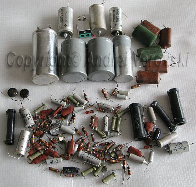
And here is a picture of components typically to be replaced in vacuum tube Pioneer. Coupling caps mentioned in one of the posts are small gray cylinders.
pioneer_sm83_old_parts_lowres.jpg
 
Ok here is a pic of the chasis that I edited for the op, he is talking to me in private but he wants to help so this is good. Thanks for all the great info posted recently. I have one resistor that looks like a 2.2 meg that is burnt and need some help to ident. here is the pic to check against in your amplifier.
 

Attachments

  • IMG_5377.jpg
    IMG_5377.jpg
    97.9 KB · Views: 84
from what I could tell from the schem it is a 15k resistor, so she is opened up and not simply beyond my meters reading ability. I hope it was from the very leaky 6be6 tube that it runs from.
 
I'm in the process of moving but I think I can still get to the Pioneer. I'll try and get into it this weekend and take a better picture you can use to see the bands and local neighborhood of this resistor.

Andy
 
Back
Top Bottom