Pioneer SX-737 audio output just stopped

BigD264

New Member
Hello, I was listening to music on my SX-737 about an hour ago and the sound just stopped. I turned off the receiver and turned it back on and... no click from the receiver at. I'm getting absolutely no audio output. I had an issue previously on the B-Channel where my right speaker would start crackling at lower volumes and at some points stop working entirely. I switched to the A channel and It was working flawlessly until now. The speakers I'm using are pioneer HPM-60's and I the receiver connected to my PC through an aux cable. I've had this repaired once before fairly recently and to have it break so soon is really frustrating. If I could pin point whats wrong I would be willing to try and fix it myself. Also I had a problem at one point where my audio would stop and the right speaker would crack and I'd get no click for a period of time. The after waiting a few minutes it would click again but then cut out after a few seconds of playback. I seemed to have fixed this by recutting my wires and making sure there were no loose threads. I figured I'd add that in here in case it's relevant.
Any incite in to my issue would be appreciated.
 
Hello, I was listening to music on my SX-737 about an hour ago and the sound just stopped. I turned off the receiver and turned it back on and... no click from the receiver at. I'm getting absolutely no audio output. I had an issue previously on the B-Channel where my right speaker would start crackling at lower volumes and at some points stop working entirely. I switched to the A channel and It was working flawlessly until now. The speakers I'm using are pioneer HPM-60's and I the receiver connected to my PC through an aux cable. I've had this repaired once before fairly recently and to have it break so soon is really frustrating.
The receiver is 40 years old. Unless it was given a major overhaul it's not terribly surprising something else would crop up.

If I could pin point whats wrong I would be willing to try and fix it myself. Also I had a problem at one point where my audio would stop and the right speaker would crack and I'd get no click for a period of time. The after waiting a few minutes it would click again but then cut out after a few seconds of playback. I seemed to have fixed this by recutting my wires and making sure there were no loose threads. I figured I'd add that in here in case it's relevant.
Any incite in to my issue would be appreciated.

Do you have any basic tools needed, and experience working with them?
 
The drop out's sound like they are most likely heat up related in the amplifier board. #1 suspects are the 2sc1451's. These are the most problematic of the problem transistors that PIONEER used in the Early 70's to late 70's amplifier boards. The symptoms are not unlike listening to a bowl of RICE KRISPIES in Milk. WHEN the 2SC1451 finally dies, it WILL take resistors, caps and other parts including the output's with it. Prior to it dying completely you will get the symptoms stated by your initial post.

The #2 suspect(s) are the 2sa726's. They aren't as bad as the 1451 but they will present with similar symptoms.
Q1-Q2-Q3-Q4 need matching per pair. They are part of the biasing circuit and affect how close you can get.
Solution is to replace them pre-emptively, and check/replace parts immediately upstream/downstream of the offenders. Also replace any 2SA725 or 2SA726 on any boards they are present on. (about 15-18 total).

These are the transistors I replaced on my 737 amp boards in early 2014. All are FAIRCHILD transistors except for the outputs MJ21193G and 21194G which are On-SEMI. All numbers noted in this post are MOUSER Numbers.

2sa726 (ecb) > 512-KSA992FBU (ln)to-92 ecb 120v .05a .5w 100mhz 150-800hfe $0.22 ea
2sc1451 (ebc) > 512-KSC3503DS or DSTU to-126 ecb 300v .1a 1.2w 150mhz 60-120hfe $0.54 ea
2sb527 (bce) > 512-KSA1220AYS to-126 ecb 120/a160 1.2a 20w 155mhz 35-320hfe
2sd357 (bce) > 512-KSC2690AYS to-126 ecb 120/a160 1.2a 20w 155mhz 35-320hfe
------- output transistors (unlikely but for completeness) -----------
2sb530 > 863-MJ21193G pnp to-3 250v 16A 250W 4mhz 8-75hfe
2sd370 > 863-MJ21194G npn to-3 250v 16A 250W 4mhz 8-75hfe

Prices above as are 01/25/2016

Pin layout LEFT TO RIGHT (Front facing you, pins to bottom)
Q1 Q2 Q3 Q4 original 2sa726 (ecb) > 512-KSA992FBU to-92 ecb is same as the original
Q5 Q6 2sc1451 (ebc) > 512-KSC3503DSTU to-92 ecb is REVERSED B and C...
Q9 Q10 2sb527 (bce) > 512-KSA1220AYS to-126 ecb is REVERSED from the original
Q7 Q8 2sd357 (bce) > 512-KSC2690AYS to-126 ecb is REVERSED from the original

Larry
 
It would be prudent to stop powering the unit on until some diagnosis can be performed. It may not have damaged anything severely - Yet. The fact that the protection relay will briefly energize tends to indicate that. The next power-up may yield different results, however.

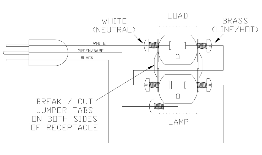
If you are going to diagnose the unit it may also be a good idea to construct a dim bulb tester and equip it with a 40W incandescent lamp to start, and possibly a 60W lamp after that. Instructions can be found in several threads on the site, or something like this:

DBT:

DimBulbTesterDiagram.jpg


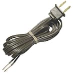
Get a short grounded cord;

0ea8cbdd-6b2a-45c6-a8be-99c452f14914_145.jpg


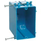
A plastic conduit box;

590c1d96-27c7-4a1f-9e67-7d0fadf1772c_145.jpg


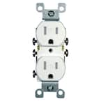
A duplex receptacle;

6448605a-b345-4a96-b319-76f30c5fd05d_145.jpg


A receptacle cover;

c12be196-cb39-4b66-a029-6c13557464f5_145.jpg


A plug-in lamp holder;

f8589964-3992-4094-ac4b-e4b5fd16fd17_300.jpg


And an assortment of incandescent lamps from 40W to 100W (or whatever is close to that in today's green world).

Without the lamps you should spend less than fifteen bucks (otherwise know as two packs of fuses, on third of a fire extinguisher, etc.).
 
The receiver is 40 years old. Unless it was given a major overhaul it's not terribly surprising something else would crop up.
Yea it's not surprising to me just frusterating, you know?

Do you have any basic tools needed, and experience working with them?
And I have general experience working with the innards of electronics, I have no parts for something like this laying around however. Unless it was something simple I would bring it to somebody who has a better understanding.

The drop out's sound like they are most likely heat up related in the amplifier board.
And that kind of makes sense. When my issues first started cropping up after I initially got it fixed, it was after I forgot to turn it off and left it on for an entire night. I turned it off and came back later and it was working again. I forgot to turn it off again and the same thing happened. Eventually however I just stopped having that issue however the right speaker would still drop out and it sounded exactly like a "bowl of rice krispies." The dropouts as I stated in the original post all stopped when I switch my speakers from the B connectors on the bottom to the A connectors on the top. Everything ran flawlessly until my audio just stopped. And by that I mean I literally didn't hear a thing from either speaker. No pops or crackling coming from them. It was like I just hit mute on my computer (and yes I did make sure that I hadn't simply muted my sounds :p).
 
It would be prudent to stop powering the unit on until some diagnosis can be performed. It may not have damaged anything severely - Yet. The fact that the protection relay will briefly energize tends to indicate that. The next power-up may yield different results, however.

If you are going to diagnose the unit it may also be a good idea to construct a dim bulb tester and equip it with a 40W incandescent lamp to start, and possibly a 60W lamp after that.
I stopped powering on the unit. It's just sitting in a sad corner until i get it fixed :(
And I might try that tomorrow. It definitely seems easy enough and worth it for sure!
 
Since you are experiencing the "rice crispies" sound in the right channel it would seem that Larry nailed it. The old transistors are beginning to get lead attachment failures. If one goes open completely it can get ugly. If one cracks and short, it can get even more ugly. Larry gave you the list of general suspects, and the replacements are literally pennies apiece. The shipping is likely to exceed the product cost, so it would be prudent to construct a fairly comprehensive list of devices to update your unit and spread the shipping cost to make it more economical. There are more suspicious devices in the unit, as well as a host of capacitors to be exchanged and items to be cleaned. There are some reliability upgrades to be performed, and adjustments to be made.

As for it being simple, if you can solder and operate a multimeter, it's going to be about as simple as that. Obviously you already posses the ability to read and post responses, so the rest will be easy. The tough part is getting as complete and comprehensive schematic diagram for the SX-737, but you can download the service manual from various sources, like this: http://akdatabase.com/AKview/displayimage.php?album=44&pos=92
So you think the "rice-crispies" from the right speaker is related to my overall sound just going on the whole receiver?
 
Mine did that. It would pop and the whole receiver would cut out. Mine was Q3 in the amp board.
 
One of those "wonderful" 726s. I've read that more commonly with the 1451s, but the 725/726 have a long RAP sheet too.
 
You have transistor leakage which is causing the protection circuit to engage and save your speaker's from DC death. The noises you are hearing if they are coming from either channel will trigger the protection relay and cut off sound to your speakers.

Larry nailed down the two big culprits in the receiver and for longevity they should be replaced. I've done dozens of Pioneer receivers from this series and the problem your having is extremely common. First thing I would do is power the receiver up with a meter across the speaker terminals looking for mvDC. This will give you a reason for the protection circuit's action. Then it's diagnosing time. The other method here is replace all of the notorious transistors and hopefully shotgunning works. Then it's on to capacitors...
 
Not sure it will work for you, but I was able to find the transistor causing my issues using compressed air, turned upside down and just a very short quick spray on the components on the amp board. I traced the circuit until I hit the one that was bad and it popped and crackled. Then I went on to the rest to see if there were others. I did this with crap speakers I picked up at GW so I would not fry my good speakers. I am not sure this method is always recommended, but in my case, it was and it helped me find the issue.

Again my issue was Q3, but those have to be replaced in matched pairs. I am currently planning to rebuild the entire receiver, but now I have a working receiver to start with.
 
Found this useful post to fix my 737. Replacing the 726 and 1451 transistors seemed to have done the job.

One important note. One of the posters notes the 2SA726 as being ECB. The ones in my unit were in fact BCE. The service manual lists them as ECB but the silkscreen and the way they were installed told me that was wrong. Confirmed the pinouts with my transistor tester.

Luckily I spotted them before I powered it up.
It's always the best advice with these old transistors and new replacement parts to use a modern transistor tester to check the pinout. I check every old one, make notes of the old pinout and compare the replacement twice before I power up.
 
I thought I would revive this thread rather than starting a new one since the title pretty much states my issue. The backstory on the unit is that about 5 years ago I did a recap and changed out all the "problem" transistors as mentioned in Post 3, except for Q7, Q8, Q9 and Q10. The unit worked for a while and then one day, lights on, but no relay click and no sound. I put it in the closet and forgot about it.

Since I now have time, this weekend I started to look at it to see if I could understand what failed. I replaced the four transistors and was going to power it up. I thought to be safe I would set the bias to 0v. Does anyone know which direction to turn the pots to get 0v bias? Measuring resistance across the pots to determine maximum resistance and therefore set the bias to 0v was not helpful. No matter in which direction I turned the wiper, resistance would be 0-ohms.

Thanks
 
If you are measuring through VR1 and VR2 for offset adjustment, there should be a change in resistance. They are only 100Ω trimmers, so lock your meter into a low resistance range rather than allowing it to auto-range. If it is truly ZERO Ω, there might be bridging on the solder connections or some similar issue.

If you are measuring through VR3 and VR4 for bias adjustment, due to the arrangement of the trimmers, one shorted trimmer will effectively short both of them.

index.php
 

Attachments

  • upload_2020-7-5_13-47-26.png
    upload_2020-7-5_13-47-26.png
    426.4 KB · Views: 104
I haven't done anything with the DC offset pots. I am trying to dial down the bias voltage. Would I need to remove the bias trimmers to determine if they are shorted? If one is shorted, would that have contributed to the loss of the audio that I experienced?

Thanks
 
If one shorted you'd get full voltage on the output's an possibly burn them out. (Something else to check too!) See this thread on BJT Testing..... https://audiokarma.org/forums/index.php?threads/bipolar-junction-transistor-testing-basics.43186/ If any on one side bad replace the whole side. They're cheap enough (price wise) but more robust than the originals. I'd replace them all and keep the good ones as spares. MG21193G & MG21194G. OR the 25G & 26G. They're basically the same for our purposes.
 
I may have less of an issue than I initially thought. I was able to get the bias and DC offset adjusted. The relay was a bit slow to engage after I got the bias adjusted, but it seemed to work okay the couple of times that cycled the unit. I'll let it idle overnight and check everything again tomorrow.
 
Back
Top Bottom