Rebuilding an Eico HF-89

goldear

Certifiable Audio Junkie
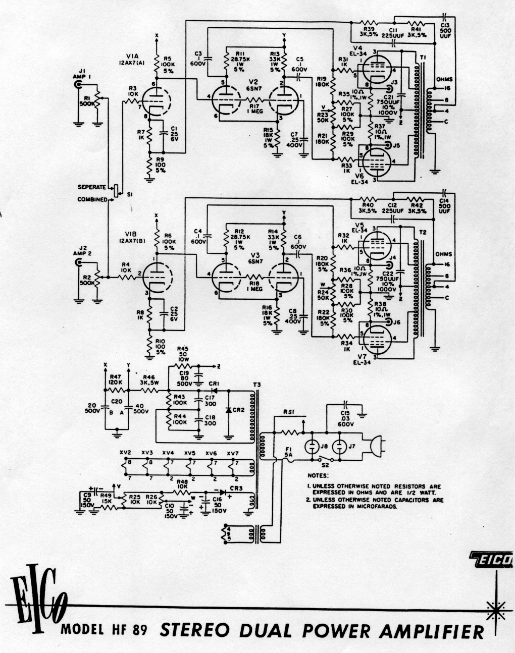
I'm thinking of doing this as a little project over Christmas break. But I have some questions for those who have some experience with this amp, or its brother the HF-87.

I already have a supply of good caps to replace the originals with. But what I'm really curious about is what your opinions are on changing-out the old Carbon resistors. My old modding rule of thumb tells me to replace these with MF whenever possible. But I'm cuirous if others have any differing opinions on this. I'm slightly concerned about making the amp too bright sounding by changing the parts recipe too much.

What about adding 100 Ohm screen resistors? Is this a good or bad idea? I know that these can really help extend output tube life, but I'm not sure what the downsides of doing this are. I'm considering doing this because this amp always seems to have the tubes right on the edge of meltdown.

I'm definitely planning on installing a polarized power cord. And I'm considering possibly trying dc heaters. But I plan to try ballancing the heaters ground reference through a couple of resistors to ground first.

I'm considering ordering a new power transformer to replace the original as well, but I think that I'm going to wait to do that later.

I'm also considering implementing a ground-bus to replace the chassis ground. But I've been advised not to do this by at least one person.

Any other ideas or suggestions? The plan is mostly simple upgrades because I like the way the the stock circuit sounds (with the exception of the hum). I'm not going to regulate anything. But would some fancy diodes for the rectifiers make sense?
 
Last edited:
The metal films are always good in my book , the 100 ohm grid stopper are a good idea .I wouldnt go with with DC fillaments on the output tubes , but if you get a better power transformer , look for one with center tapped filament windings and a bias tap .I prefer a star ground over a a ground buss and better diodes never hurt .
 
If I were rebuilding the HF-89, I would gut it, clean refinish parts as nec. Replace ALL resistors, caps, diodes with fast recovery, tube sockets with QUALITY sockets such as Belton, Angela, etc and don't use gold plated!

Use the original manual to reassemble. I would not change the orig grounding scheme, you could open a big can of worms.

The EL34's are run very hot, 63ma bias current. It even says in the manual that red spots on the plates is normal! I would bias them no more than 50ma or expand the bias and use KT88 or 6550 tubes.

Just my $.02!
 
A comprimise on the resistor thing might be carbon film. You get better stability, accuracy and noise figures than carbon comp, but they are supposed to sound more like the old style. I've never back to back compared them though, so I really don't know how much can be heard from different resistor construction methods.


Why are you planning to replace the power transformer, upgrade or is the original toast?
 
Here, this may come handy:
hf89schematic.jpg

more data at http://sanacacio.net/hifi/hf89.html
 
I hope that Dave Gillespie weighs in -- he has a lot of experience with this amp.

On my HF87, I did a number of things, including:

1. Created a fixed bias circuit with 10K bias adjust pots;
2. Added screen resistors;
3. Added a 12V CT transformer for the 12AX7;
4. Rebuilt all of the cans;
5. Replaced the two doubler caps with higher-value, modern caps;
6. installed a choke in the B+ circuit;
7. Replaced the rectifiers with soft recovery types;
8. Installed constant current sources for the splitter / driver

If it were me, I'd leave the carbon comps in the grid and cathode positions, so long as they were within spec.
 
Goldear -- Adding the screen stability resistors to this amplifier is absolutely mandatory. Likely more than any other amplifier, the Eico HF-89 has the nastiest of reputations for eating output tubes -- not because of the high plate dissipation called for, but because of the circuit conditions that exist that promotes arc events in the output tubes. Eico tried to resolve the issue (in part) with the release of the HF-89A, but with little success -- this because their fix did not address the core issues involved.

This amplifier served in part to help develop some of the material I gathered when I wrote my original article on output tube arcing some 7 years ago now. It is that article where the concept of adding screen stability resistors is first offered to curtail such events. To date, I am not aware of any comments regarding any negative impact they have on the sound, with virtually all saying that they are audibly invisible. If you are interested, you can find the article here:

http://www.tronola.com/html/maximize_tube_life.html

There were minor circuit differences between the HF-89 and the HF-89A, so you will want to identify which version you have to make sure that you are using the correct schematic for the unit you have. Since there were no chassis changes to easily identify which version is which, you will need to do a little detective work. The easiest way to identify which unit you have is to look at the primary leads of the OPTs on your unit. If they have two B+ leads per transformer, then it is an HF-89. If they only have a single B+ lead, then it is an HF-89A.

Good luck with your amp!

Dave
 
goldear,
I've worked on on HF-87 and I've built an amp from scratch that is based on the Eico HF-87/ST-70 amps using the ST-70 OPT's and 6l6GB's. The HF-87 had a small bit of background noise/hum, but the scratch amp was so quiet on Klipsch La Scala's that you had to put your ear close up to the mid's and tweeters to hear a very faint rushing sound. It uses AC filaments and a ground buss with the various parts of the circuit connected in a quasi star ground arrangement to the buss. It is mostly KOA carbon film in the signal path and is very detailed yet smooth at the same time on the Klipsch's. I'm not a horn fan, but I may have been able to live with this combo. I think the owner is very happy. I also used some of Dave Gillespie's suggestions i.e., screen stoppers, etc. Thank you Dave for your article on power tube life.

I can send you a schematic and some pictures if you like.

All the best for your project,
John
 
For those of you who say to go with the original grounding configuration, how about replacing those nasty-looking RCA jacks? The grounding appears to be simply via chassis contact. I've never seen any other design do this.
 
Goldear -- Adding the screen stability resistors to this amplifier is absolutely mandatory. Likely more than any other amplifier, the Eico HF-89 has the nastiest of reputations for eating output tubes -- not because of the high plate dissipation called for, but because of the circuit conditions that exist that promotes arc events in the output tubes. Eico tried to resolve the issue (in part) with the release of the HF-89A, but with little success -- this because their fix did not address the core issues involved.

This amplifier served in part to help develop some of the material I gathered when I wrote my original article on output tube arcing some 7 years ago now. It is that article where the concept of adding screen stability resistors is first offered to curtail such events. To date, I am not aware of any comments regarding any negative impact they have on the sound, with virtually all saying that they are audibly invisible. If you are interested, you can find the article here:

http://www.tronola.com/html/maximize_tube_life.html

There were minor circuit differences between the HF-89 and the HF-89A, so you will want to identify which version you have to make sure that you are using the correct schematic for the unit you have. Since there were no chassis changes to easily identify which version is which, you will need to do a little detective work. The easiest way to identify which unit you have is to look at the primary leads of the OPTs on your unit. If they have two B+ leads per transformer, then it is an HF-89. If they only have a single B+ lead, then it is an HF-89A.

Good luck with your amp!

Dave
Thanks Dave! I think that this was the second time that I have read your article. Thanks for making a really meaningful contribution to discovering why modern tube amps so often eat output tubes! My unit will definitely get screen resistors now.

Out of curiosity: Does anybody have an HF-89A schematic? I've only ever seen the original schematic, and I have no idea which of the two models I have. Are the changes made to the later model helpful at all? Can these be incorporated into the earlier design or not?

One of the big issues which I want to try to attempt to resolve with this amp is hum when it is connected to any other component which happens to grounded. The polarized cord should help in this regard, but I'm virtually certain that this will only lower, not eliminate the ground-loop hum which I am hearing.

Could you or anybody else please explain what the purpose of that .03uF cap from the line to chassis-ground is? I'm presuming that this was done for safety or something. But what purpose does it really serve in this circuit? Wouldn't eliminating this cap eliminate the hum caused by the ground-loop which its creates?

Some people have suggested DC filamnets are a solution to hum. But when this amp is dead quiet when it is not inadvertently grounded through another component, this approach doesn't really make a lot of sense to me.
 
DC heaters makes the most sense in a phono stage and possibly in preamp tubes. In a power amp thats halfway well designed it should make no appreciable difference. If it doesn't hum on it's own, I would expect no change going from AC to DC heaters. The humming only if grounded through another component has all the markings of a ground loop.

One thing that might be of use is hanging a pair of 100 ohm resistors, one from each side of the heater supply to chassis. That will balance the AC voltage relative to chassis ground and should help null out any hum noises that it would introduce.
 
The purpose of the .03 cap is to establish the ground level potential of the chassis.

While the chassis establishes a ground plane for the wiring and components contained within it, the actual ground potential of the chassis is not established due to the isolation created by the unit's power transformer. Since the electrical power distribution system represents absolute ground relative to all mains induced noise, using a small cap to tie the chassis to one side of the AC line then helps to reduce any radiated 60 Hz noise that the chassis might otherwise act as an antenna to pick up. The cap simply locks the chassis to an absolute ground level.

In the days when this equipment was produced, there were no polarized power outlets or green wire ground systems in place. Therefore, there was a 50-50 chance as to which side of the line the cap might be connected to. When a unit was used standalone, it typically did not matter which way the plug was inserted, because even though the neutral side of the line represents the low earth point, both sides of the AC power distribution system still in fact represent a very low impedance path to ground with regards to noise. Therefore, even if the cap ended up being connected to the hot side of the power system, it still produced lower noise than with no cap at all.

However, when multiple units containing these caps were all connected together, hum levels rose if all the caps did not reference the same side of the AC line, so endless trials of reversing the plugs for each piece of equipment ensued to achieve the lowest noise levels.

With the coded requirement of polarized outlets today, it allows such nonsense to be a thing of the past. Ideally, all of the old equipment that mingles the electrical and chassis grounds together (as virtually all the old equipment did) should be converted to a polarized two wire line cord with the internal AC bypass cap connected to the lead representing the neutral side of the line. That way, the lowest noise configuration will automatically be achieved when multiple pieces so converted are connected together in a system. It is also important to use a modern safety cap designed for such service (i.e., one that fails open) which will then provide maximum safety with this approach as well.

This approach is eminently more preferable than converting all such equipment to a three wire power cord ground system. That approach is a recipe for hum disaster with the ground loop that is form between the chassis ground connection of the audio cables, and the chassis ground connection of the green wire ground system. It is perfectly fine to have ONE piece of equipment in fact tie the system to the power outlet ground system, but never more than one. Today, since it is an almost guaranteed certainty that the ground side of all cable or satellite systems do in fact represent the AC ground system as well, it is best to let that equipment be the green wire grounding point of your system when you connect it to these devices.

This is hardly meant to disparage the green wire ground system. However, to use that approach effectively would require you to isolate circuit ground from chassis ground in each piece of the old equipment, which physically they were not designed to accommodate with regards to low noise. Using a two wire polarized power cord system will minimize the noise and provide more than ample safety when configured as discussed.

The other point of hum generation in the HF-89 is the unbalanced heater supply used to power the heater of the 12AX7 AF amplifier tube. This is supplied by a small auxiliary power transformer underneath the chassis that has one side of it's secondary winding grounded. A significant reduction in hum can be obtained by breaking that ground connection, and returning both sides of this heater supply to ground through a 390 ohm 1/2 watt resistor. The resulting balanced operation (with respect to ground) will then provide the lowest noise level possible from an AC supply, of which the improvement is particularly notable at mid level control settings. A DC supply will improve the noise level even further, although simply converting the existing AC supply to a balanced system will often provide very acceptable results even with sensitive speakers.

Dave
 
Why? Gold is an excellent conductor and doesn't corrode. That should lead to better connections over the lifetime of the socket

Indeed gold is a good conductor, but this is more of a quality issue. The "gold" plating is super thin and delaminates easily causing all sorts of electrical gremlins, usually where you solder it to a pcb.
 
Why? Gold is an excellent conductor and doesn't corrode. That should lead to better connections over the lifetime of the socket.


And most of the stuff sold today that advertises gold plated is just rubbish that may be gold plated. The contacts are usually so thin that they break or just bend the first time used. That goes for audio cables as well. You are not talking much loss in the connection as the marketing department may want you to think. IMHO, you can't beat the old Switchcraft, Amphenol etc. quality if it is in good condition (read NOS ;))
 
Actually gold is not as good a conductor as copper. Gold is used in plating (quality use that is) because it will not oxidize so the connection is stable over a long period of time. When soldering a connection, it is not needed as long as you clean the parts before soldering as the solder will create an airtight seal around the joint, preventing corrosion. When the connection is ment to be made and then disconnected, like cable connections, plug in circuit packs etc, then glod plating makes some sense.

Shelly_D
 
indeed. Gold's big advantage is the resistance to corrosion. Copper and silver are better conductors, but both oxidize.
 
The purpose of the .03 cap is to establish the ground level potential of the chassis.

While the chassis establishes a ground plane for the wiring and components contained within it, the actual ground potential of the chassis is not established due to the isolation created by the unit's power transformer. Since the electrical power distribution system represents absolute ground relative to all mains induced noise, using a small cap to tie the chassis to one side of the AC line then helps to reduce any radiated 60 Hz noise that the chassis might otherwise act as an antenna to pick up. The cap simply locks the chassis to an absolute ground level.

In the days when this equipment was produced, there were no polarized power outlets or green wire ground systems in place. Therefore, there was a 50-50 chance as to which side of the line the cap might be connected to. When a unit was used standalone, it typically did not matter which way the plug was inserted, because even though the neutral side of the line represents the low earth point, both sides of the AC power distribution system still in fact represent a very low impedance path to ground with regards to noise. Therefore, even if the cap ended up being connected to the hot side of the power system, it still produced lower noise than with no cap at all.

However, when multiple units containing these caps were all connected together, hum levels rose if all the caps did not reference the same side of the AC line, so endless trials of reversing the plugs for each piece of equipment ensued to achieve the lowest noise levels.

With the coded requirement of polarized outlets today, it allows such nonsense to be a thing of the past. Ideally, all of the old equipment that mingles the electrical and chassis grounds together (as virtually all the old equipment did) should be converted to a polarized two wire line cord with the internal AC bypass cap connected to the lead representing the neutral side of the line. That way, the lowest noise configuration will automatically be achieved when multiple pieces so converted are connected together in a system. It is also important to use a modern safety cap designed for such service (i.e., one that fails open) which will then provide maximum safety with this approach as well.

This approach is eminently more preferable than converting all such equipment to a three wire power cord ground system. That approach is a recipe for hum disaster with the ground loop that is form between the chassis ground connection of the audio cables, and the chassis ground connection of the green wire ground system. It is perfectly fine to have ONE piece of equipment in fact tie the system to the power outlet ground system, but never more than one. Today, since it is an almost guaranteed certainty that the ground side of all cable or satellite systems do in fact represent the AC ground system as well, it is best to let that equipment be the green wire grounding point of your system when you connect it to these devices.

This is hardly meant to disparage the green wire ground system. However, to use that approach effectively would require you to isolate circuit ground from chassis ground in each piece of the old equipment, which physically they were not designed to accommodate with regards to low noise. Using a two wire polarized power cord system will minimize the noise and provide more than ample safety when configured as discussed.

The other point of hum generation in the HF-89 is the unbalanced heater supply used to power the heater of the 12AX7 AF amplifier tube. This is supplied by a small auxiliary power transformer underneath the chassis that has one side of it's secondary winding grounded. A significant reduction in hum can be obtained by breaking that ground connection, and returning both sides of this heater supply to ground through a 390 ohm 1/2 watt resistor. The resulting balanced operation (with respect to ground) will then provide the lowest noise level possible from an AC supply, of which the improvement is particularly notable at mid level control settings. A DC supply will improve the noise level even further, although simply converting the existing AC supply to a balanced system will often provide very acceptable results even with sensitive speakers.

Dave
Thanks so much for explaining that. I'll definitely be balancing the heater's ground reference in addition to using a polarized plug.

I'm presuming that all amps which feature a voltage-doubling circuit would be somewhat inclined to hum if connected to a grounding component because the secondaries would be connected to the chassis. Is this correct? If that's true, then I find it strange is that my Citation II doesn't hum at all when connected in the same manner, but it features a voltage doubler circuit.
 
Another question for you guys: Is there a need, or is it desirable to replace the bias and/or balance pots? These seem like they might be tricky to find compatible replacements for.
 
With regards to the AC grounding issue, it matters not which kind of rectifier scheme is used -- that is, whether the HV winding is actually grounded or not. With a HV doubler circuit, one side of the HV winding connects to a a big ol' fat cap, the other side of which is grounded. This cap (being one of the doubler caps) provides an extremely low impedance path to ground AC wise, so for the purposes of hum reduction, the winding is effectively grounded with this scheme as well.

It is certainly desirable to clean up and check the health of the bias pots. If need be, the original pots can be removed, disassembled, cleaned, and lubricated as necessary. In doing so, I've never had any issue with the original pots, although others may know of a good source to replace them if that is your goal.

Dave
 
Back
Top Bottom