
I havn't had any problems so far with the 5AR4, but then I don't usually run the amp at high volumes. But when I do I tend to think about the 5AR4 being over taxed.I'm using the VTA ST-70 with KT-88's and I'm using the Genelex 5AR4 with NO problems.

You are using an out of date browser. It may not display this or other websites correctly.
You should upgrade or use an alternative browser.
You should upgrade or use an alternative browser.
Rectifier Tube
- Thread starter canton
- Start date
triode17
Super Member
But what if the rectifier shorts?Sigh. No, that analysis is 100% incorrect.
You know the rectifier has failed because the B+ STOPS. The solid-state diodes are wired in series with the tube rectifier's pins. The purpose is to take up the slack in reverse voltage, as this stresses a tube rectifier but not the solid-state rectifier. The 0.7 VDC voltage drop from solid-state, by the way, is negligible for B+ so it can be ignored.
All current flows through the tube, cathode to plate. All of the current. Every single electron.
So, no, the voltage does not suddenly rise if the rectifier fails, and there is no safety drawback. The advantage is extension of the tube rectifier's lifespan, always a good thing as rectifier tubes cost real money.
triode17
Super Member
I've measured the current to the output transformers and it comes to 250ma per channel. That's 500 ma total, on a 225 ma rectifier, AT MAX RMS POWER.
So, if you don't regularly push it hard to full power, the 5AR4 should be OK. Yes it would be better to have two but where to put it?
So, if you don't regularly push it hard to full power, the 5AR4 should be OK. Yes it would be better to have two but where to put it?
sKiZo
Hates received: 92644 43.20°N 85.50°W
I never put the 5AR4 back in after that but went to a 5R4GYB when I found it had the 2A filament and a bit more drop that just adds more margin.
Tried a 5R4GYS here and it lasted about a week - bias kept dropping until it just went belly up. Wondering if it was a bad tube or if there's some fundamental difference between a GYS an GYB ...
PS - that particular Phillips tube was advertised as the greatest thing since the whoopie cushion. Got it, stashed it during the build, and seller gave me a too bad, so sad when I tried to get it replaced. (mutter mumble)
I've measured the current to the output transformers and it comes to 250ma per channel. That's 500 ma total, on a 225 ma rectifier, AT MAX RMS POWER.
So, if you don't regularly push it hard to full power, the 5AR4 should be OK. Yes it would be better to have two but where to put it?
That's where things get interesting here, as I tend to push it hard with prog rock to ridiculous levels, using expansion AND bass synth. Can't seem to be able to hurt the amp, no matter how I try ... ;-}
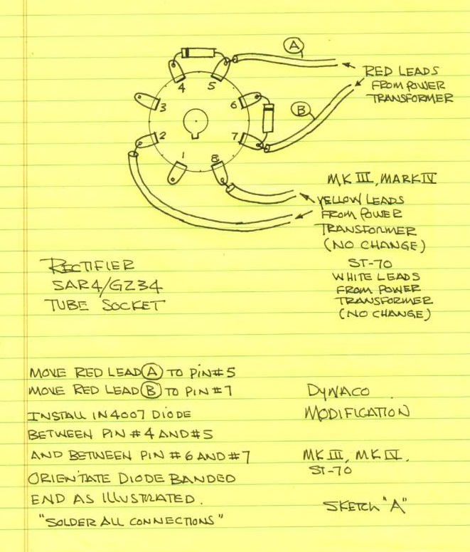
Oh. Another helpful hint - if you haven't already done so, DO the "yellow sheet mod". As mentioned, reverse current is a killer, and you can prevent that with the simple addition of a couple diodes on the rectifier socket.
Last edited:
But what if the rectifier shorts?
At first I thought you meant the solid-state rectifier. You mean the tube rectifier, right?
Tube rectifier shorts when using solid-state protection diodes are very rare. The normal mode of failure is the tube rectifier's cathode normally loses emissions or the filament opens; in both cases the rectifier ceases to conduct. If the rectifier shorts and dumps raw AC into the filter capacitors you have a whole 'nother problem beyond rise in voltage.
But, having said that, the reverse voltage is what blows up rectifiers, so by trading risk for something which is incredibly rare (short) for something which is regular (reverse voltage every cycle) seems, well, misguided. The normal situation (without diodes) is that the rectifier tube must continually resist the flow of current for a potential difference between B+ and the AC voltage at the peak of the negative cycle. That's roughly double B+. This stresses the insulation and blows up rectifiers via flashover. The Chinese and Sovtek rectifiers are notorious for this failure mode.
I dug out the AK thread about this for you:
See Dave's comment here:
This is for the Dynaco ST-70 but it applies to any tube rectifier.
triode17
Super Member
Yes, what if one or both sides of the rectifier should short from cathode to anode? That's what I was concerned about. Then, the diodes in series with the plates will take over and do the rectification. Won't the B+ rise? This is what I thought the series diodes are for, as a failsafe.At first I thought you meant the solid-state rectifier. You mean the tube rectifier, right?
Tube rectifier shorts when using solid-state protection diodes are very rare. The normal mode of failure is the tube rectifier's cathode normally loses emissions or the filament opens; in both cases the rectifier ceases to conduct. If the rectifier shorts and dumps raw AC into the filter capacitors you have a whole 'nother problem beyond rise in voltage.
airtime
Super Member
I've taxed my amp a number of times and no problems so far.I havn't had any problems so far with the 5AR4, but then I don't usually run the amp at high volumes. But when I do I tend to think about the 5AR4 being over taxed.
whoaru99
Epic Member
I've taxed my amp a number of times and no problems so far.
Unless your amp runs full class A, current draw during music playback may have some high peak demands but the average draw is much lower in most cases. Even cranked WFO, so to speak, music playback tends to be much lower average draw than continuous rated power draw. That's probably at least part of the reason they last when it seems at the surface maybe they shouldn't.
This is what I thought the series diodes are for, as a failsafe.
The series diodes are to unload the inverse voltage from the tube rectifier. The SS diodes handle the inverse, the tube is basically just a time delay resistor. I suppose if it shorted you'd see B+ jump but I really wouldn't expect the rectifier tube to short out since its not doing a whole lot of work, particularly in a Mark IV like originally discussed. In the ST-70 its still being beaten up with forward current though. Subbing an actual resistor would take care of that though. If you do it right, you could fit the diodes to the bottom of the socket, make yourself up a plug-in that contains the drop resistor, and then you could swap from SS to vacuum rectifier with no modifications.
The series diodes are to unload the inverse voltage from the tube rectifier. The SS diodes handle the inverse, the tube is basically just a time delay resistor. I suppose if it shorted you'd see B+ jump but I really wouldn't expect the rectifier tube to short out since its not doing a whole lot of work, particularly in a Mark IV like originally discussed. In the ST-70 its still being beaten up with forward current though. Subbing an actual resistor would take care of that though. If you do it right, you could fit the diodes to the bottom of the socket, make yourself up a plug-in that contains the drop resistor, and then you could swap from SS to vacuum rectifier with no modifications.
Agreed Gadget in all counts.
Like a Weber copper plug, but be aware these plugs get super hot as the resistor inside gets hot, and at the end damage the SS diodes inside.
There is no magic, ohm law is at play here, and power dissipated has to go somewhere.
I guess that cooling fins on the weber would help it survive longer, SS diodes don't like heat.Agreed Gadget in all counts.
Like a Weber copper plug, but be aware these plugs get super hot as the resistor inside gets hot, and at the end damage the SS diodes inside.
There is no magic, ohm law is at play here, and power dissipated has to go somewhere.
A cooling fan that blows on the weber would also do, we are talking about app. 15w of heat.
triode17
Super Member
OK, I stand corrected.The series diodes are to unload the inverse voltage from the tube rectifier. The SS diodes handle the inverse, the tube is basically just a time delay resistor. I suppose if it shorted you'd see B+ jump but I really wouldn't expect the rectifier tube to short out since its not doing a whole lot of work, particularly in a Mark IV like originally discussed. In the ST-70 its still being beaten up with forward current though. Subbing an actual resistor would take care of that though. If you do it right, you could fit the diodes to the bottom of the socket, make yourself up a plug-in that contains the drop resistor, and then you could swap from SS to vacuum rectifier with no modifications.
If you do it right, you could fit the diodes to the bottom of the socket, make yourself up a plug-in that contains the drop resistor, and then you could swap from SS to vacuum rectifier with no modifications.
Yes, but a B+ delay is beneficial to avoid cathode stress in other tubes by forcing it to pass current before the space cloud is complete and the islands of charge have coalesced. Yes, tubes are robust and, yes, it takes a number of on/off cycles with premature conduction to damage the tube. But given the cost of most output tubes, anything which extends tube lifespan is cash money.
Like a Weber copper plug, but be aware these plugs get super hot as the resistor inside gets hot, and at the end damage the SS diodes inside.
Just a point of clarity. Most of the Weber Copper Cap Rectifiers are only for guitar use because the device replicates the tube's characteristics of voltage vs current, so increased current causes voltage sag. Only one is for HiFi use, and it comes with and without a thermistor to serve as a B+ delay.
So the dropping resistor for the guitar units and the thermistor for the HiFi unit might explain why the device becomes so hot.
Yes, what if one or both sides of the rectifier should short from cathode to anode? That's what I was concerned about. Then, the diodes in series with the plates will take over and do the rectification. Won't the B+ rise? This is what I thought the series diodes are for, as a failsafe.
Yeah, ok, I see your potential voltage rise and raise you protection circuitry.
Put a high-voltage Zener diode in as a failsafe, add an LED (with dropping resistor) and optional buzzer to the output. That way if an over-voltage condition occurs it means the rectifier has failed and the solid states are running, so the voltage has climbed to a higher than acceptable level, the Zener prevents damage, and the LED and buzzer warns the operator of the condition. DONE.
Using the Zener to drive a high-voltage MOSFET to reduce heating of the Zener is left as an exercise for the reader. Using a string of Zeners to reduce the noise is also an exercise for the reader, but this is just pointless as the point is a fail-safe device, so deterioration of the sound from Zener noise is a bonus warning. Adding a B+ delay, with a time-constant to prevent oscillation, in case of the failure is also left as an exercise for the reader.
Edit: fixed typos.
Last edited:
Yes, but a B+ delay is beneficial to avoid cathode stress in other tubes by forcing it to pass current before the space cloud is complete and the islands of charge have coalesced. Yes, tubes are robust and, yes, it takes a number of on/off cycles with premature conduction to damage the tube. But given the cost of most output tubes, anything which extends tube lifespan is cash money.
In a Mark IV I probably wouldn't do this, but in an ST-70 where the rectifier is really run beyond what it can actually handle the resistor would provide somewhat more available current to the output stage to help with full power output performance. A time delay can be added, it just makes things more complicated than a simple resistor does.
These are different issues.
I agree that the ST-70 places too high a demand on the rectifier and that the solution is changing to either:
Current limiting to avoid rectifier stress, however, is different than warm-up delay, and the latter has some overlap with the inverse protection mechanism.
The point I was making was in the context of using rectifier diodes to take up the inverse slack and the safety features to minimize risk of tube damage from premature B+ when the tube has failed and the entirety of the rectification is performed by the solid-state diodes. (Mutatis mutandis as per the above.)
I agree that the ST-70 places too high a demand on the rectifier and that the solution is changing to either:
(a) dual tube rectifier (what McIntosh contemporaneously used)
—or—(b) solid-state rectifier with a warm-up delay.
Current limiting to avoid rectifier stress, however, is different than warm-up delay, and the latter has some overlap with the inverse protection mechanism.
The point I was making was in the context of using rectifier diodes to take up the inverse slack and the safety features to minimize risk of tube damage from premature B+ when the tube has failed and the entirety of the rectification is performed by the solid-state diodes. (Mutatis mutandis as per the above.)
Indeed, different problems and different amps. The ST-70 is just what folks usually think of when they think Dynaco and 5AR4 issues. It probably should have had a dual rectifier, but short of a modern trafo with more current capacity on the 5v heater winding I don't know that its possible to do that. A modern one, sure. Stab the second rectifier socket where the can cap is, move the caps underneath to a terminal strip and you're in business. Short of that, you're stuck with SS rectifiers, a suitable drop resistor, and a time delay if you wish to add that into the mix.
The Mark IV effectively has dual rectifiers though. One Mark IV is a single channel of the ST-70 with a dedicated rectifier for that channel. As such its living a fairly comfortable life and should hold up very well.
The Mark IV effectively has dual rectifiers though. One Mark IV is a single channel of the ST-70 with a dedicated rectifier for that channel. As such its living a fairly comfortable life and should hold up very well.
sKiZo
Hates received: 92644 43.20°N 85.50°W
Truth be told, they're all for hifi use ... if you ignore the new warnings on the website. Those were just added recently when they revamped to keep their little litigators happy. I'd still go with the WZ68 any day if I were to want a solid state replacement. Same price as the WZ34 (once recommended as a GZ34 replacement), yet twice the power rating. Got one in the kit for a last chance spare if I manage to blow up all the bottles.
PS ... seems to me it's not a resistor that gets hot in these things, it's a thermistor. Yeah, I know, semantics. Anyway, that's one disadvantage of using the WS1 they now recommend for hifi - no thermistor, so you lose the slower startup and surge protection you get with the WZ34 and WZ68 or most bottles used in these amps.
Oh - also hear tell of folk who've drilled the bottom and top of copper tops to add cooling by convection with good results. The copper top is press fit, but pulls off pretty easy for the machine work.