Replacing The STV-3H and -4H Diodes

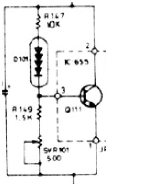
>probably to use a transistor

It is more than the output trans in some cases . You need to count the number of b-e juctions the diodes are biasing. We need to compensate for the sum total b-e.

Right. Sometimes a diode is added in series with the bias tracking transistor, though not mounted on the heatsink. Sometimes a Darlington transistor is used.
 
Here's a variation on the theme, from a Carver amp.:

Bias.jpg

Only the transistor is mounted on the heat sink. The advantage of this design is that if the pot opens up, the transistor is biased full on, and no current flows through the output stage. In circuits where there is just a diode(s) and resistors, if the pot opens up, full current is allowed to go to the output stage and blows the outputs.
 
Here's an assembly I made using three 1N3595's. They were put together lying parallel to each other, with a lead bent 90° and soldered to the adjacent diode. I should have taken a pic before I covered the whole thing with JB Weld, but alas...

The assembly is mounted onto a ring terminal (#4 hole) with the crimp section opened up and flattened out. Not the neatest job, but it was my first.

JBDiode_01.jpg

JBDiode_02.jpg
 
Last edited by a moderator:
Vbe multiplier

Here's an assembly I made using three 1N3595's. They were put together lying parallel to each other, with a lead bent 90° and soldered to the adjacent diode. I should have taken a pic before I covered the whole thing with JB Weld, but alas...

The assembly is mounted onto a ring terminal (#4 hole) with the crimp section opened up and flattened out. Not the neatest job, but it was my first.

Looks neat enough to me, nice job. Im going with a TIP31A Bipolar transistor as a Vbe multiplier with a couple of resistors around it so it acts like three diodes, Im not sure if I am explaining it very well but Im sure you understand what Im trying to say.
 
Here's an assembly I made using three 1N3595's. They were put together lying parallel to each other, with a lead bent 90° and soldered to the adjacent diode. I should have taken a pic before I covered the whole thing with JB Weld, but alas...

The assembly is mounted onto a ring terminal (#4 hole) with the crimp section opened up and flattened out. Not the neatest job, but it was my first.

This looks great, but I have one concern: JB Weld has steel in it, I believe. Is the stuff conductive? Have you installed the assembly yet and tried it out?
 
Thermally conductive epoxy would do a good job, maybe even fashion it into a horseshoe type shape to fit them like they originally were. They will obviously be bigger, but there won't be a need for an insulator compared to the crimp lug method echowars showed.

I take it this would work with stvh-2, depending on the diodes, of course.
 
Last edited:
>mounted onto a ring terminal
Looking good and neat, too bad the crimp section is not long enough to wrap around the diodes. looking foward to your test result when you get around to it.

>Vbe multiplier with a couple of resistors around it so it acts like three diodes
Please show a schematic, I don't get the whole picture.
 
This looks great, but I have one concern: JB Weld has steel in it, I believe. Is the stuff conductive? Have you installed the assembly yet and tried it out?
JB Weld has no actual steel content that I'm aware of (despite the 'steel' label of one of the two component tubes). It hardens as a tough plastic, and conducts heat very well.
>mounted onto a ring terminal
Looking good and neat, too bad the crimp section is not long enough to wrap around the diodes. looking foward to your test result when you get around to it.
No need. If the parts are clean, JB Weld is pretty tough stuff, and the end result isn't going anywhere. And the cured resin does a good job of transferring heat.
>Vbe multiplier with a couple of resistors around it so it acts like three diodes
Please show a schematic, I don't get the whole picture.
See dr*audio's Post #24 for an example. This is a much more complex solution than replacing a diode, and the transistor must be in contact with the heatsink of the output devices. There are some amps where this is a good alternative, and others where is would not work so well for various reasons. But in order for it to be considered the driver board and the heatsink for the output devices must be within a reasonable distance of each other.
 
Wraping the diodes with part of the metal bracket gives better thermal coupling a % point or two. It is a bit more sturdy physically incase the epoxy got loose. Both not much of concern with your pictures. It is a pain in the tail to do any more than using a plain lug.

The good doctor's post I do understand. It has good features as describled and is a bit more complex. It still uses diodes for temp compensation. The calculation is not as straight forward as plain diodes.
 
dr*audio's example is a little unusual in that it uses a multijunction diode as well as a transistor. Most bias servo setups do not.
 
This looks great, but I have one concern: JB Weld has steel in it, I believe. Is the stuff conductive? Have you installed the assembly yet and tried it out?

I tested that a while back, I took a pair of #24 bare copper wires, and made 2 parallel lines 1/16 of an inch apart, then dribbled a jbweld puddle onto them and let it harden.

Then after it hardened, I tested resistance, and leakage current with up to 30 volts across the wires. Nada. down to the microamps.

I tested it because, when the leads break off flush with the stv-xh body, I dig down to good wire (~1/32"), solder on flexible leads and jbweld it all together.

Send me your busted diodes, and I'll try the same for you, I'm actually getting good at it, and have made a mold.

fixed-stv4h-diode.jpg
 
Last edited:
  • Like
Reactions: trs
Thanks, Mark! Well that settles the JB Weld question AND provides another solution. Cool!
 
I tested it because, when the leads break off flush with the stv-xh body, I dig down to good wire (~1/32"), solder on flexible leads and jbweld it all together.
attachment.php

Now that's a good idea. I had one break a couple of weeks ago. Couldn't bear to toss it out so I still have it. Always good to have a spare.

- Pete
 
Here's an assembly I made using three 1N3595's. They were put together lying parallel to each other, with a lead bent 90° and soldered to the adjacent diode. I should have taken a pic before I covered the whole thing with JB Weld, but alas...

The assembly is mounted onto a ring terminal (#4 hole) with the crimp section opened up and flattened out. Not the neatest job, but it was my first.

OK, the real-world test results are in for the home-made STV-4H from echowars. The amp used is the L-05M mono amp by kenwood.
After about 10 mins of warm-up the bias became stable. No problems.
I let it play for about 2 hrs and still no problems. I had the other amp with the stock STV-4H in it to compair and they behaved the same.
This test result is for the kenwood mono amps. These amps run cool, so results for another kind of amp may be different. Also, I am using vandersteens which present an easy load.
Well, There you have it. Success! :music:
Well done EW! :banana:
 
Good to hear, but as I intimated in my email, the real test is what happens to the bias when the amp is really pushed and gets hot. Not easy to do at home.
 
This is where a temperature chamber comes in handy and which no one has at home.

As a suggestion one can use the refrigerator to get the cold end (32 F?) and the oven (not too hot 110 F?) for the high end. One can get 3 data points cold, room and hot. The temp range would cover more than what an amp sees.

You can put the home make, the real one, and 3 b-e juctions under bias in the simple temp test. If the amount of volt change matches the 3 b-e changes then we have a winner.
 
I was thinking of immersion in vegetable oil and heating whilst measuring temp with my laser thermometer.
 
That gets great even temp distribution. You get a more accurate temp reading than what I was thinking in free air. I think oil is a good insulator at this kind of volt.
 
Back
Top Bottom