Rotel RX-830 instantly burned the fuses

rotco

Active Member
Hi all,

I've got this Rx with that issue it's automatically burned the main two fuses.
i've got a recommendation to begin with the 4 output transistors (to220).

i took them all out together with the heat sink. i tested each of them and i think they are fine.
(im afraid i didn't understand 100% how to check if they are good or not)
meantime, another guy here on AK recommend me using "Dim Bulb Tester".
so, i make myself one, with 60W bulb (My country is 230V).

I turned ON the Rx, while all the transistor and heat sink are dismantled. (see pic attached).
Im not sure if my conclusions are correct, so i wanted to ask for your help.

in this case while i turned ON the Rx, the bulb was lighted with healthy power, which means i have a short in the RX.
from here, i assume that the short is in the circuit somewhere "before" the output transistors.
because, otherwise, in this scenario, i would expect to get an open circuit, isn't it?! (question #1)

if so, where else can i look for the shortage? (question #2)

Thanks

P.s
I wasn't sure whether it's a good idea to power ON the Rx while its not "complete" (transistors dismantle) but i did it... hope it doesn't might make any other faults in the Rx

transistors just hanging like that for shot the picture. i will use the insulators later.
WhatsApp Image 2018-06-01 at 15.11.02.jpeg
 
Commonest shorts are output transistors (which you already checked) and rectifiers (I believe it is four legged module near the fuses on the board). Other possibilities are shorted filter caps and pinched wires - both rare but....).
Also, be aware the metal tabs on the output transistors are connected to the collectors, which is why there should be insulators and an insulated shoulder washer for the mounting screws)
 
Can you link to the Service manual or schematic?

Sometimes just doing passive tests you can find a short circuit. If resistance between 2 points with high voltage is very low or near zero, there is a short. Exception are the transformer windings, which can read low ohms but that's normal.
 
@sregor rhx for the S.M.
@elnaldo can you refer to few specific suspect components?
I think the rectifier is the most suspect now isnt it?
Also, i wonder if resistors and capacitors may be shorted. For some reason in my mind i think they might be "open" but not shorted. I probably wrong with that assuming.
 
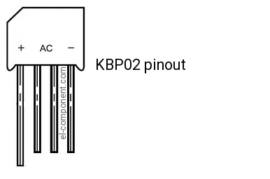
Please check the rectifier or just replace it. If you replace it, pay attention to ~ terminals and + and -. Some rectifiers have different pinouts, but it's always written on the rectifier body.

Are those missing fuses what blows? Or the main fuse before the transformer?

Suspect components are mostly semiconductors, but I ve seen shorted capacitors, even film and multi layer ceramic, or solder bridges and loose wires.

Start with the simplest, perhaps the rectifier is bad.

You can measure continuity from the fuse holder to ground (without power, just passive tests ), and from the + and - rails to ground (+ and - terminals in the rectifier). If you have continuity, there is a short circuit. Leave the meter connected for some seconds to charge a bit the main capacitors. Large caps measure a short to the meter for the first second.
 
Last edited:
I did some measurements (power cord out of the wall)
i found continuity between the secondary transformer points (red leads), and the third one (black lead). all the three points shorted between them, and sorted to the chassis (ground).

if i understand correctly, the two ends of the secondary (red wires getting into the fuses) should be shorted.
but the black lead, should be standing for itself?
from the schematics attached, i'm not sure if all the three leads out of the transformer should be the same of not.
but, the fact that they are all together shorted with the chassis, that i believe is the fault.
i dissattached the transformer housing from the chassis just to make sure maybe its body is shorted, nothing change.
so, i that mean i have a short inside the transformer? between red wires to the black wire?
is the black wire should be zero potential (shorted to chassis ground) ant that's the reason i got continuity from red to chassis?


1.JPG 2.jpg
 
kbp02-pinout.jpg


This thing is what you need to test next, labeled d904 in the schematic. Testing the red and black wires will all be almost a short. The black wire is the center tap, part of the secondary.

Oh, the black wire is probably connected to ground, so it would be normal to have a connection to ground on the secondary.
 
Last edited:
do i have to take it off the PCB?

while connected, i found a sort between the + leg to the ~ leg (not the adjacent one, but the far one).
can i refer that its faulty or should i still have to take it out in order to know that?
 
Hi,
i replaced the rectifier, which was faulty.
Now, i turned ON the RX, thru a DBT.
Left channel works great.
Right channel is shorted.
i got a fully bright lamp while i connect speaker to the right channel.
but, if a speaker isn't connected to the right speakers terminal, the bulb remains dim (almost OFF)

what can i infer from this scenario?
before i re-installed the 4th transistors, i checked them and they were fine. also, i payed attention while installing them with insulators, silicon pads, and solder the pins carefully without shorts or open circuits.

What do you think it could be? which test may i do in order to track the culprit?
thanks
 
I'd do this:

- check DC at the output, no speakers connected. If high, don't connect any load (speakers) until fixed.

- uninstall output transistors in that channel, repeat your test (DBT + Speakers, no signal, just to see if the short is present)

-check voltages at the power amp board, comparing both channels, specially at driver transistors, Base collector and emitter
 
Dc can be lots of things. I would change input pair (q604 and 608 I believe) in any case, as they sometimes will test ok but cause offset problem, and are usually damaged when amplifier does put out DC voltages.As mentioned, bad driver, or predriver (VAS) and bad diode or resistors. Low value resistors are more suspect. Good luck with it.
 
Thanks all guys
I will try and give an update soon


But, when can i understand from that fact:
Wothout the speaker i cant see a clue to short..
But when the speaker connected to the R terminals, there is a short.

My common sense will tell it's something related to the speaker itself.. Caouse without it's presence there is no short.

I know that the speaker itself is fine and not the proplem.
 
By the way

I gave a quick test now, you were right.
On left channel i have 0vdc.
On right channel i got 25vdc!!
 
uninstall output transistors in that channel, repeat your test (DBT + Speakers, no signal, just to see if the short is present)
If ill take out the 2 output transistors, wouldn't it make an open circuit to the speakers?

-check voltages at the power amp board, comparing both channels, specially at driver transistors, Base collector and emitter
what are the driver transistors in this receiver? sorry for this silly question.. but i still not sure which transistors doing what.
that's what i thought i will do.. although it's seems like really hard job. track the line from the inputs, and comparing voltage in few points, comparing R to L, until i find the first difference.
do you think it's practical?
 
If ill take out the 2 output transistors, wouldn't it make an open circuit to the speakers?


what are the driver transistors in this receiver? sorry for this silly question.. but i still not sure which transistors doing what.
that's what i thought i will do.. although it's seems like really hard job. track the line from the inputs, and comparing voltage in few points, comparing R to L, until i find the first difference.
do you think it's practical?

It's not a problem to have the outputs out of the circuit, the output transistors manage the high currents to the low speaker resistance (few ohms), but without the outputs the circuit should work (it won't handle large currents, so don't play loud music with speakers. Listening through headphones should be fine when the high DC is fixed).

The driver transistors are Q614 and Q616, please refer to the schematic, so we can point to components without doubts, and in case you want to trace back from the output, you can see what component you need to check.

I see in you very 1st pict a little "crowded" board, wires, bent resistors, please make sure everything is properly connected and you don't have a physical short circuit, some part , screw or wire touching what it shouldn't, and check for solder bridges. Suspect of everything you did and you don't trust.
 
Hi guys,
Updating you

Thanks to you, i done with it!
Before i checked the rectifier, i took off all the 4 output transistors.
After i reinstall new rectifier, which was the culprit, i resolder all the tranaistors.
Then ive got 25vdc on right channel.
I found that collector pin of q620 dosent have the same vdc as q619.
So i found that the soldering didnt thouch well the pcb printed circuit.
I resolder the point.. And it fixeddd!

Thanks guys
 

Attachments

  • 20180629_023126.jpg
    20180629_023126.jpg
    42 KB · Views: 11
Back
Top Bottom