Sansui AU-101 - bias adjustment?

drabina

AK Subscriber
Subscriber
I have a Sansui AU-101 amplifier. The amplifier board has two variable 200 Ohm resistors (Q801 and Q802). Does anybody know if they are there to adjust bias? My DC offset is nice at 4mV on each channel but I am curious why they put the VRs there since there is no mention of bias adjustments in the service manual.

Here is a part of the amplifier board schematic with one of the VRs circled:
schematic

Thanks.
 
They are there to adjust the bias. The earlier AU101's did not have these bias adjustment pots.

The AU101 is a capacitor coupled amplifier, so the offset measurement is not as critical as in direct coupled amplifier output stages.

There are two ways of checking/setting Bias in the AU101. You can remove the fuses F002 and F003 and use a multimeter set to measure DC milliamps in place of the fuse, this will give you the actual bias current. The other way is to measure the voltage across either of the 0.5 ohm 2 W output transistor emitter resistors in each channel. Bias current is derived from the voltage measured divided by the resistance, for example 7mv measured across either of the resistors would equate to a 14ma bias current, and this should be approx what the bias current for this amp should be.

Edit: this should be a 10mv reading across the emitter resistor for the correct bias current of 20ma, see post further on in this thread

Cheers

John
 
Last edited:
Thanks for quick reply John. I still had the amp open so I took the measurements. Here they are:

Fuses removed, both channels at 45V (yes, that's Volts)

Across resistors left channel at 18.7mV and right channel at 21.8mV.

Are you sure that the measurement taken with fuses removed should show mV readings? The amplifier plays and operates just fine so I assume that everything is in order. I took the measurements with nothing connected to the amp (no speakers, no source), volume at 0 and tone controls in the middle positions.
 
Hi,

The measurements I described are an "either or".

Either

1. Measure the current at the fuse (fuse removed and meter set to measure milliamps in place of the fuse) for each channel,

or

2. With the fuses installed, measure the DC millivolts across either of the emitter resistors for each channel.

and if you are going to try both measurements, make sure that the meter leads are changed to measure volts or amps at the appropriate time
 
The measurements I described are an "either or".
That's what I did. I basically run two different measurements (not both at the same time). It is kinda strange that with the fuse removed I get volts not mV.

Also looks like my bias is about twice what it should be.

Though, before I start adjusting things, I may want to find a replacement variable resistors because the original ones look kinda tired.
 
If you are doing the fuse removed method, you should have the meter set up to measure DC milliamps, not millivolts. The meter when set up to measure milliamps effectively takes the place of the fuse, allowing current through to the amp circuit via the meter. If you have the meter set up to measure volts across the fuse receptacle you will effectively be measuring the power supply voltage (which is around 45 volts in the 101).

Agreed, the bias current looks about twice what it should be based on the emitter resistor millivolts reading.
 
Thanks again for the explanation. Now, I know why my readings were in the 45V range.

I will replace the trim pots first and then adjust the bias to 10mV.
 
r. I took the measurements with nothing connected to the amp (no speakers, no source), volume at 0 and tone controls in the middle positions.

I think you need some load on the speaker terminals, resistors or at least 8 ohm speakers. Selector on aux and volume down. I think you're checking idle current at the fuses. Could be wrong of course but something to check into.
 
Thanks for the suggestion. I have some high wattage 8Ohm resistors that I could connect as dummy loads.
 
Hi,

The dummy loads are not really necessary when adjusting bias on the 101, the settings you had - volume at zero, speaker selection at off, AUX input selected with nothing connected to the AUX inputs are fine for bias setting.

Your thread inspired me to dust off one of the AU101's I have on the repair rack and get it up and running, and bias was all over the place and was difficult to set with any accuracy. Replaced the bias pots with 25 turn items, and the bias is now reasonable stable and can be set easily (note - you will need to let the amp stabilise for at least 10 mins before setting the bias, and the bias will continue vary around a little bit over time, but should stay around where it was set).

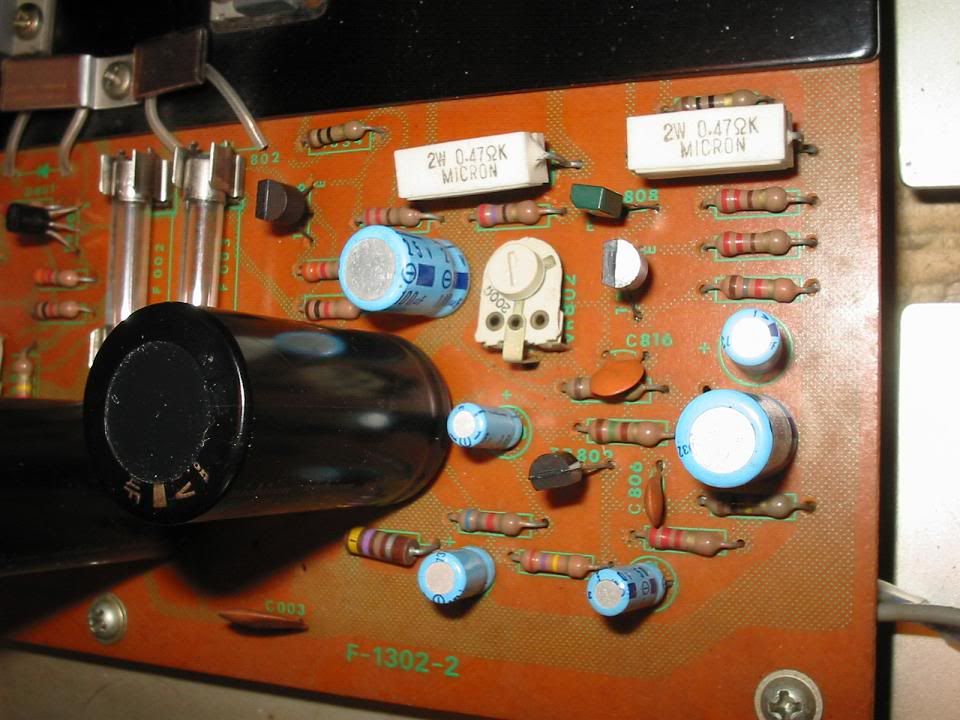
Old Bias pot

au101oldbiaspot.jpg


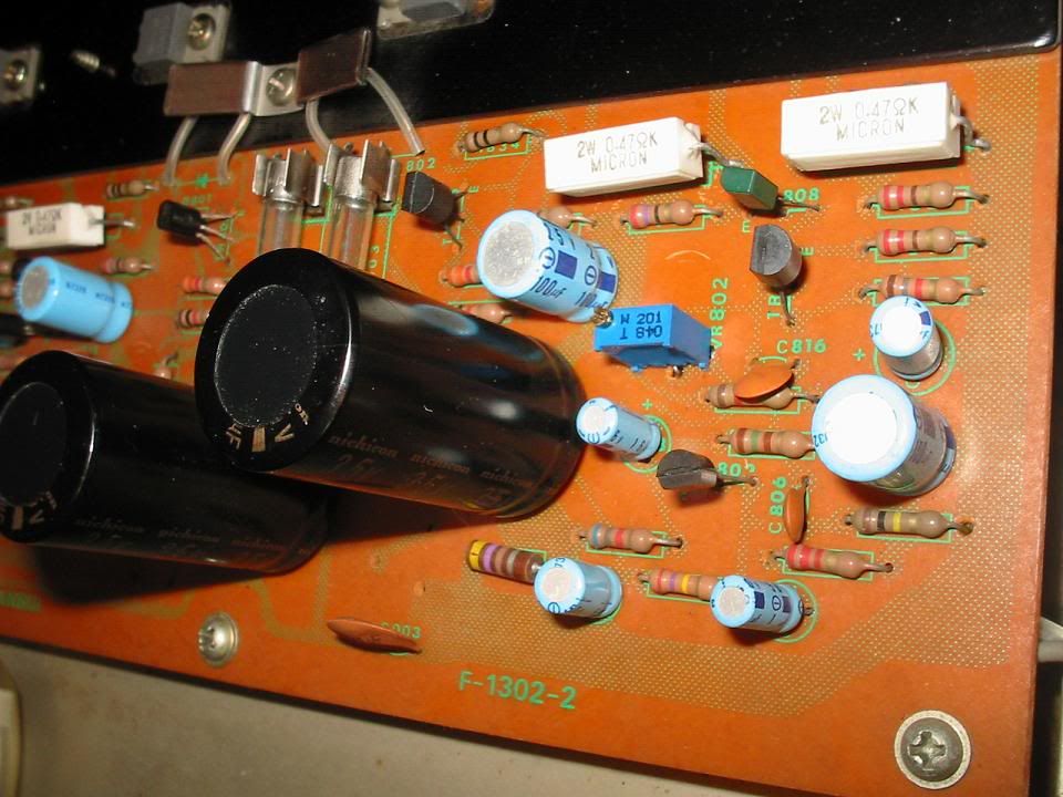
New Bias pot installed

au101newbiaspot.jpg


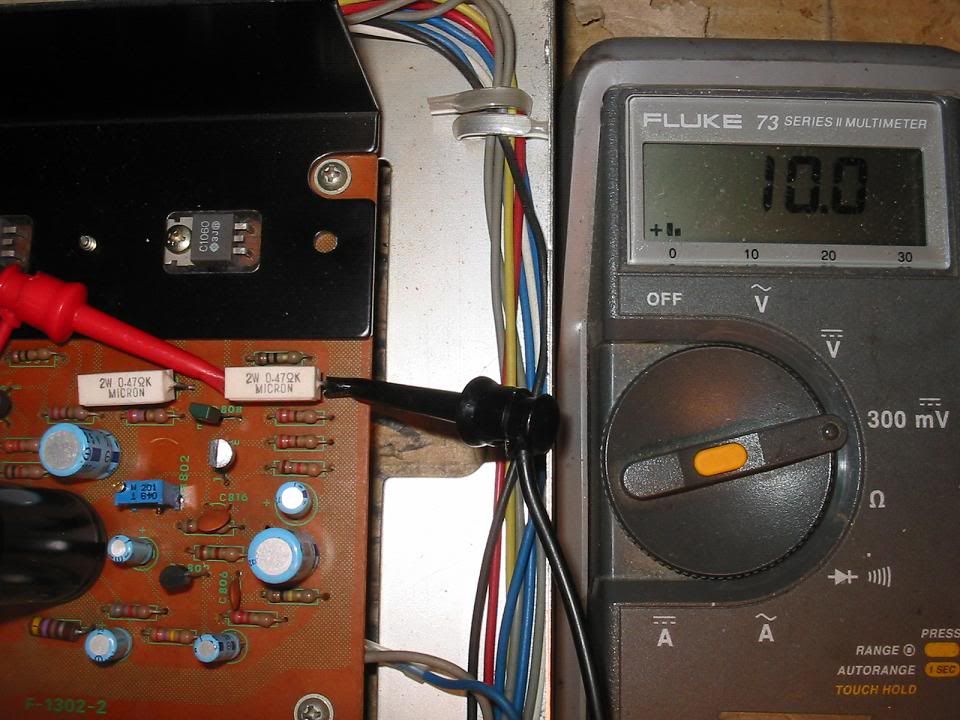
Setting Bias (note the schematic shows 0.5 ohm resistors, this 101 had 0.47 ohm, if you wanted to be pedantic then the voltage should be set to 9.4mv for 20ma bias)

au101biasadjust.jpg


Cheers

John
 
Bringing this back from the dead for a quick question :)

Does it matter which side the +/- leads are on the emitter resistor when measuring the bias? Question applies for this amp, and any amp in general.

Can someone clarify this really quick?
 
Bringing this back from the dead for a quick question :)

Does it matter which side the +/- leads are on the emitter resistor when measuring the bias? Question applies for this amp, and any amp in general.

Can someone clarify this really quick?

For this measurement the probe polarity is not important, however you might find that you need to swap them round if using an analog meter. The numerical value of the voltage across the resistor is what counts.
 
Thank you for the clarification Hyperion

I think this au101 is the perfect amp to learn. I even plan on doing my first recap and replacing the flying saucer transistors eventually. Perfect piece to get my feet wet in the upgrade hobbying
 
Hi,
I have a Sansui AU 101. The version with the trimpots to adjust the bias but no emitter resistors. On this amp you can't set the bias to 20mA. Even when you increase the resistance of the trimpot to the max (200 ohm). The bias was actually set to around 9mA when I first checked it. I found a couple of threads suggesting to use this value on other vintage audio forums. I have used the amp for a little while now and 9mA seems to work well for this particular version of the Sansui AU 101.
Cheers
Julien
 
Back
Top Bottom