Kale
Super Member
I have been away from that forum for some time, but now I have some interesting pictures to show you... it is about a really big Sansui AU20000 restoration job...
So maybe I will not finish today with posting all pictures, but tomorrow I will... so...
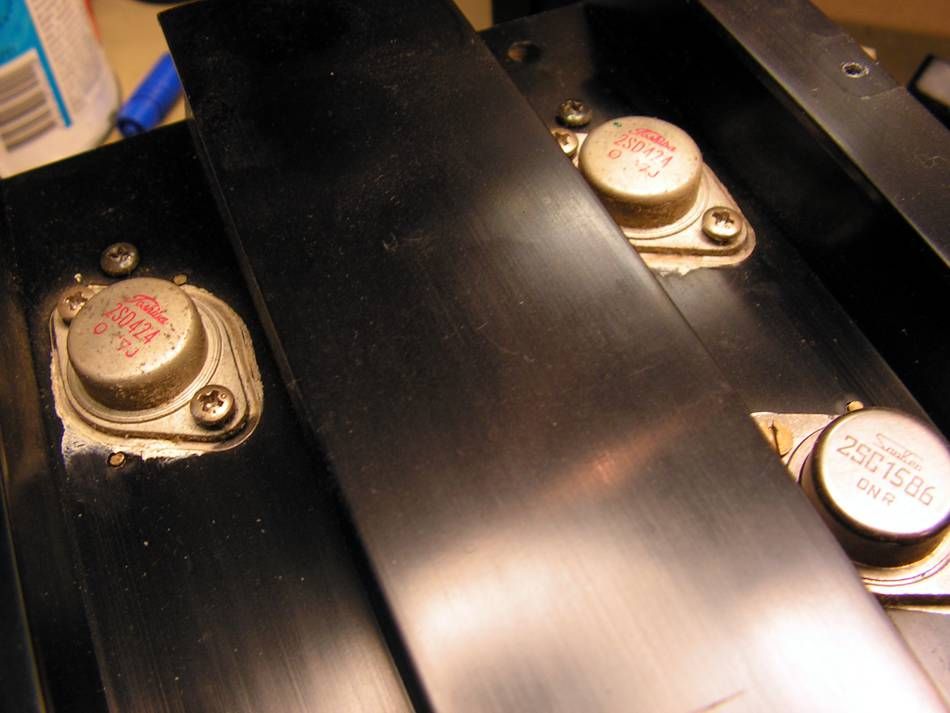
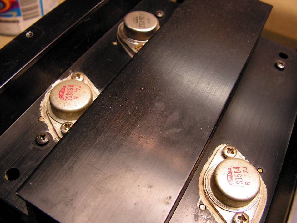
This is the first picture, about what amplifier I am talking here
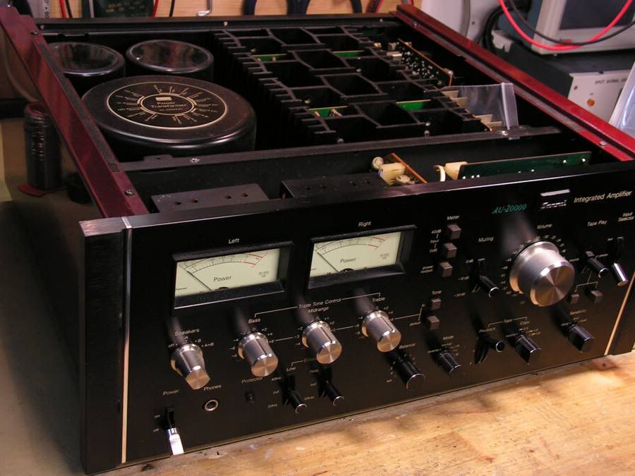
It is really nice amplifier, but it has a problem, it stays in protection mode...
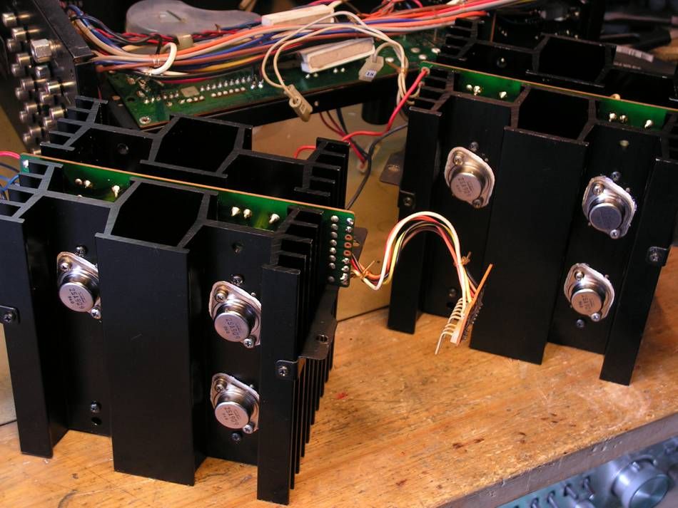
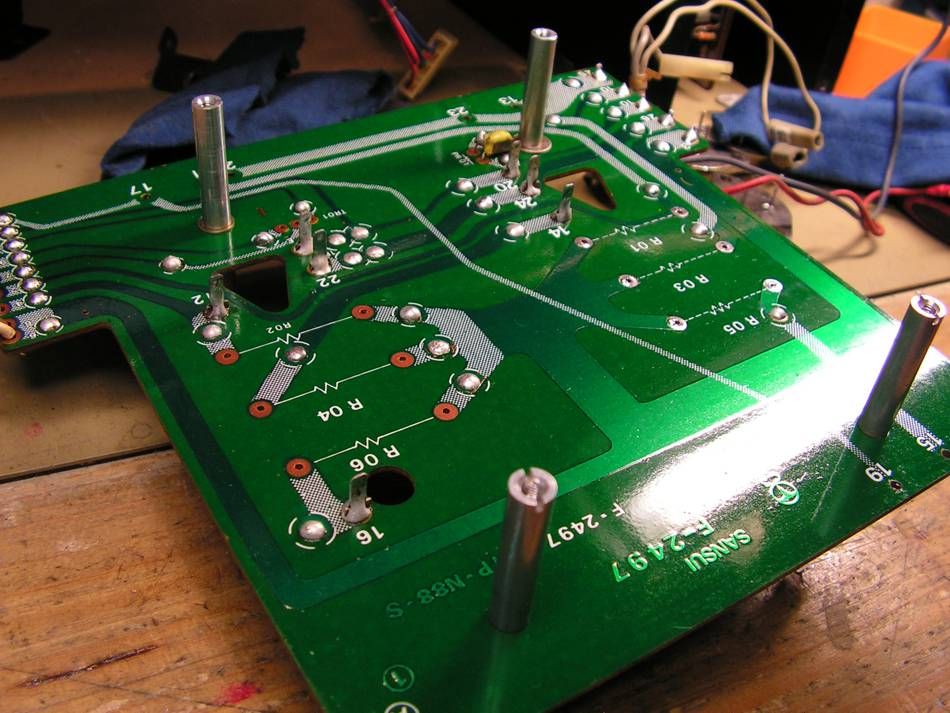
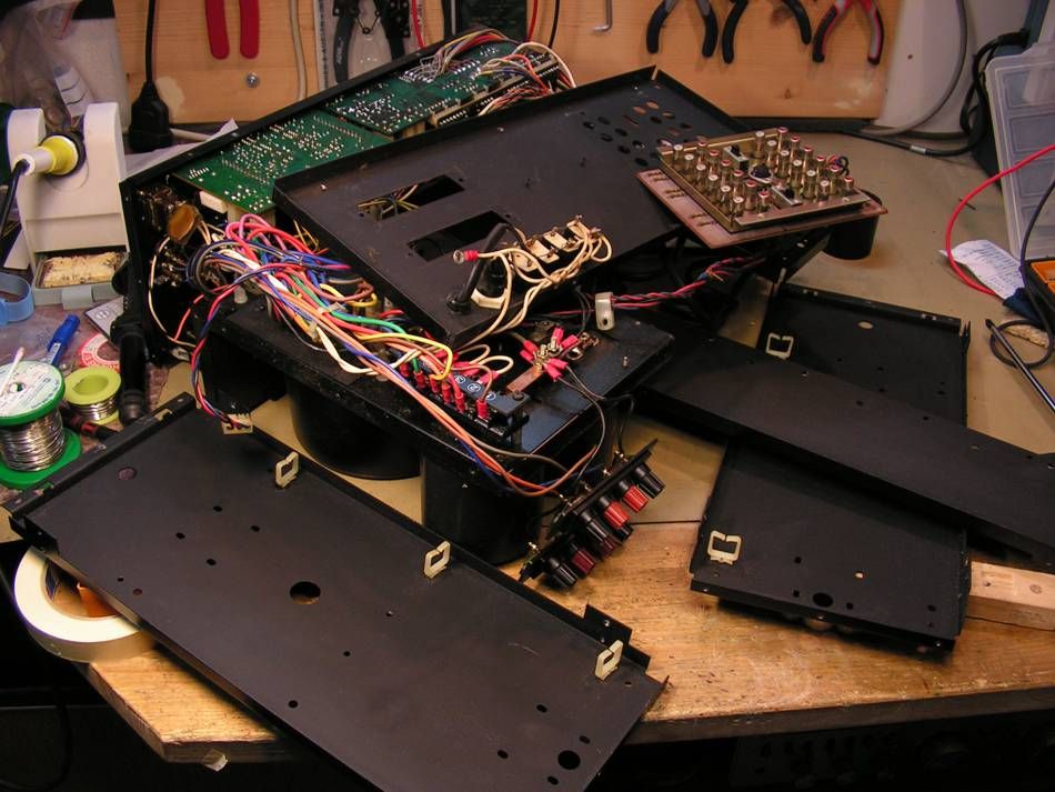
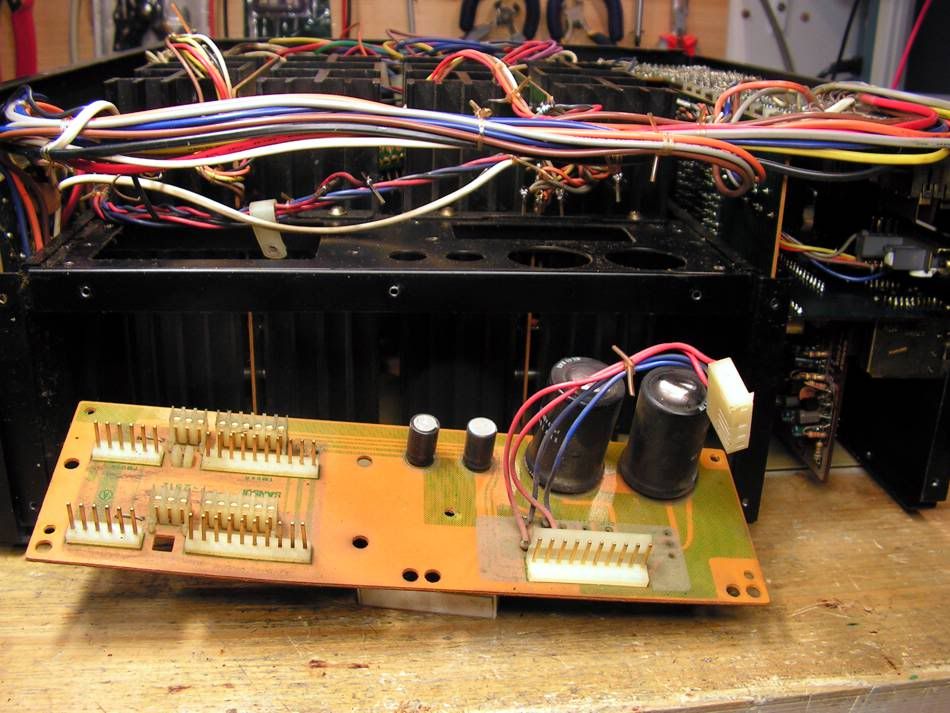
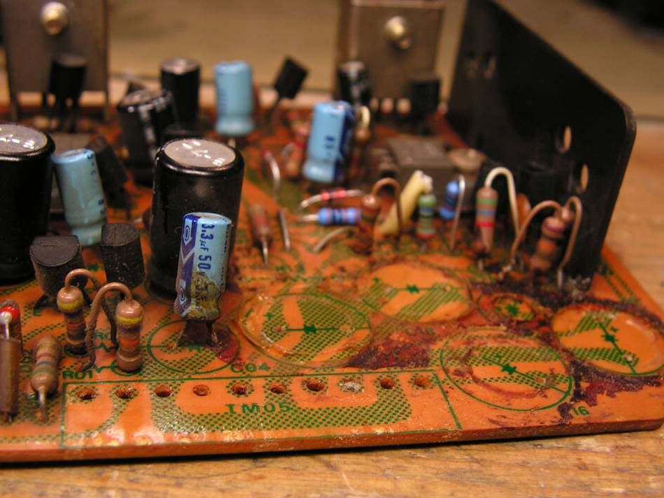
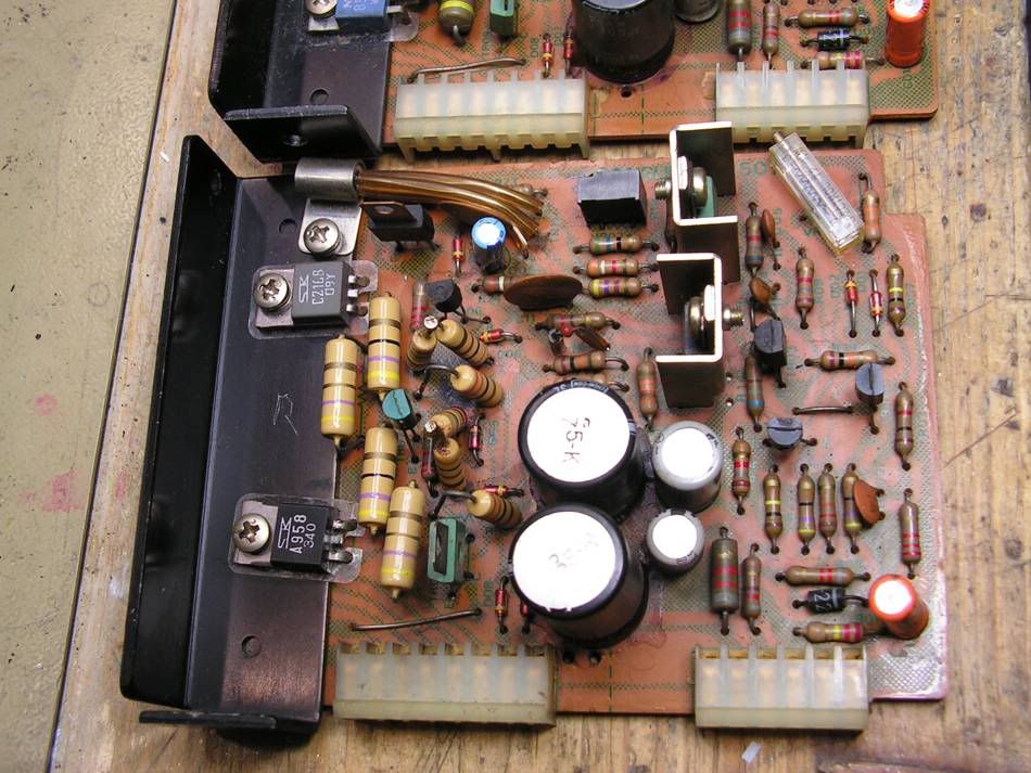
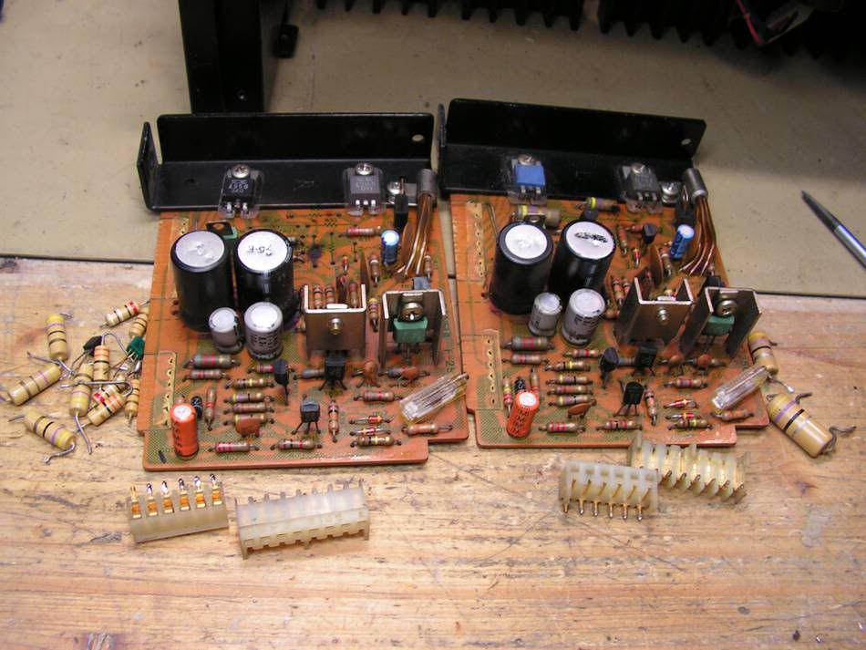
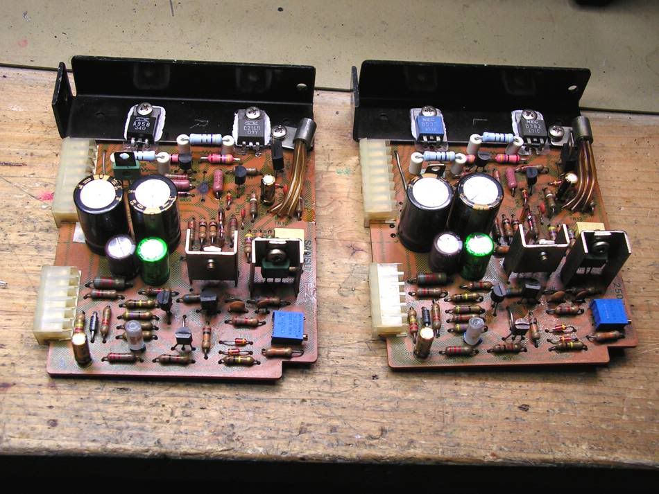
So my restoration has started with this board:
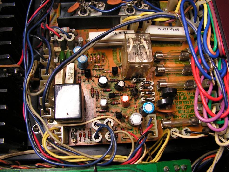
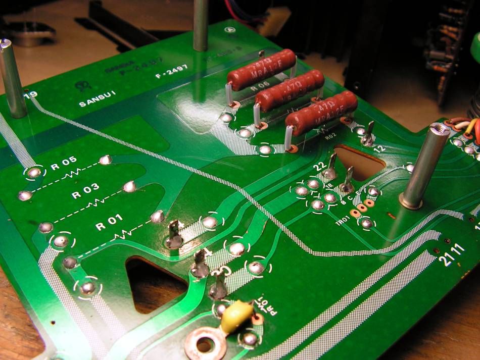
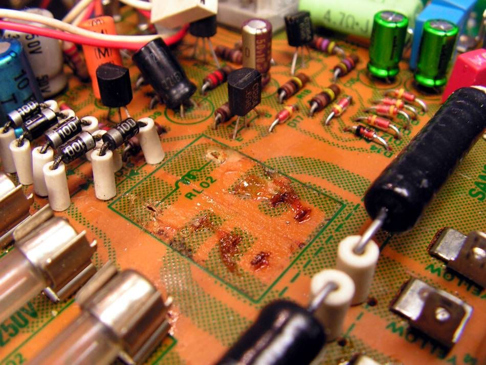
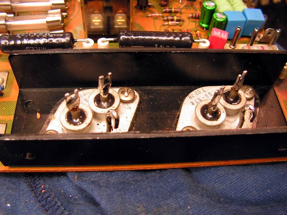
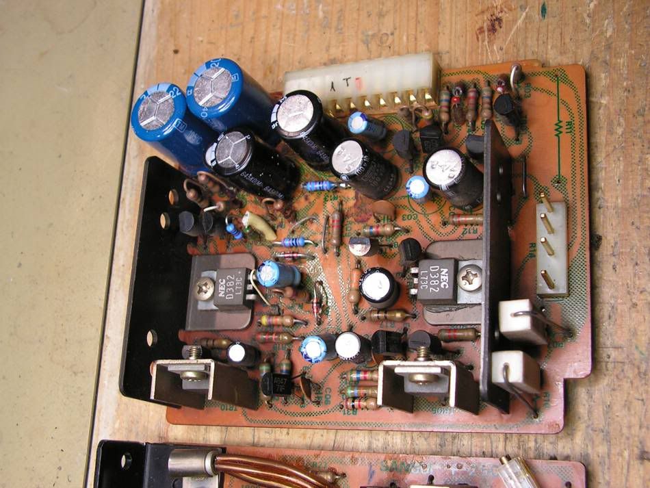
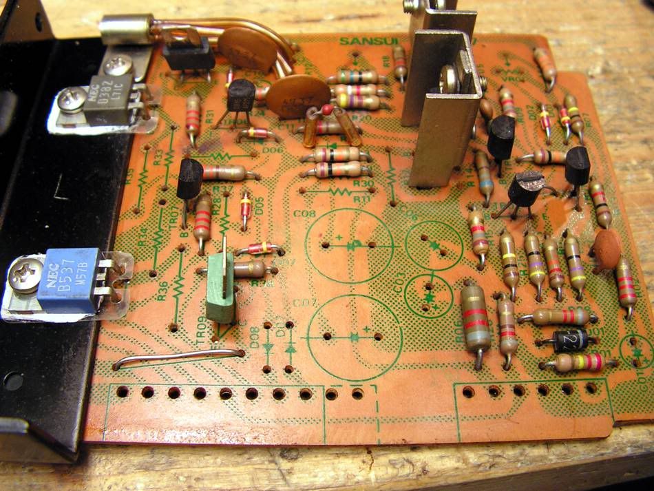
This is a board where is the main rectifier and where is protection circuit
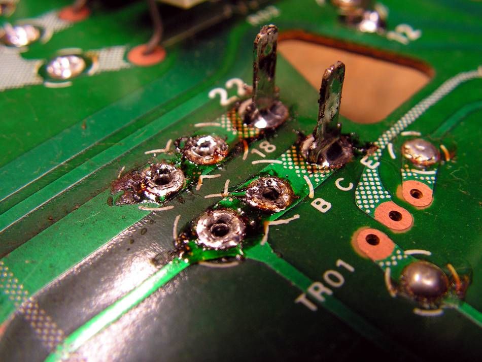
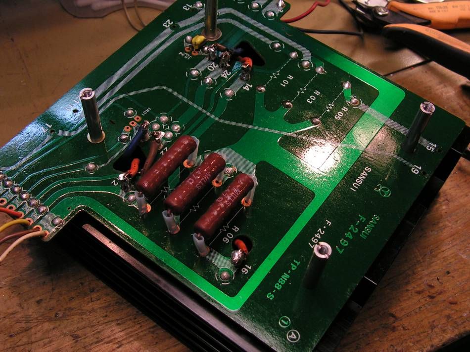
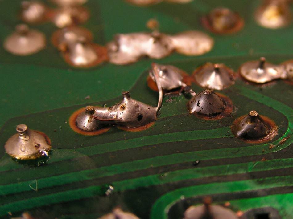
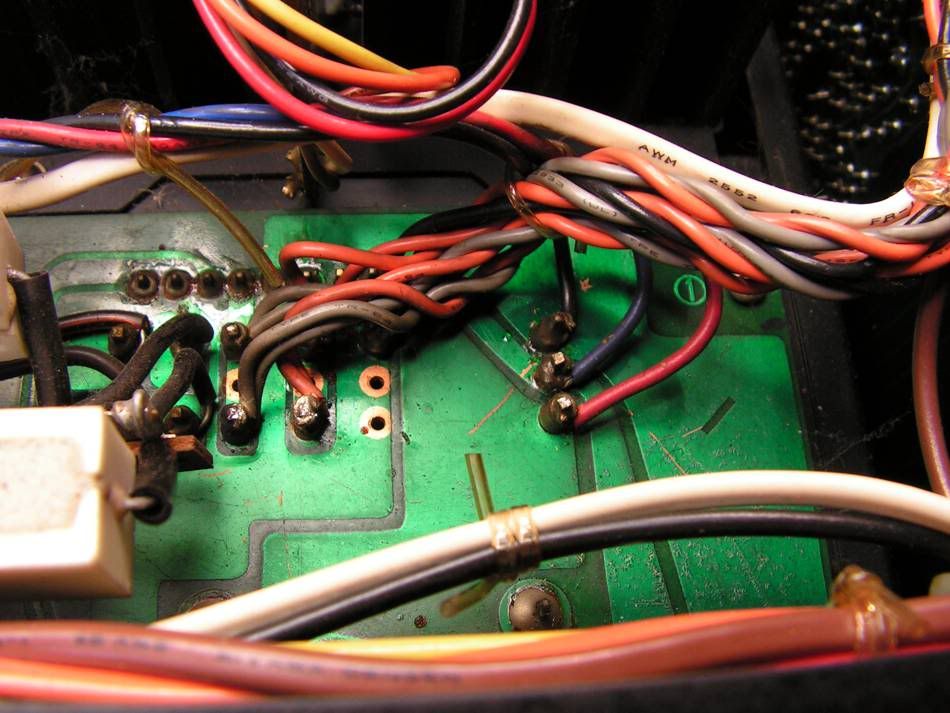
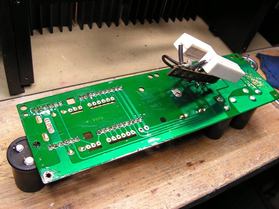
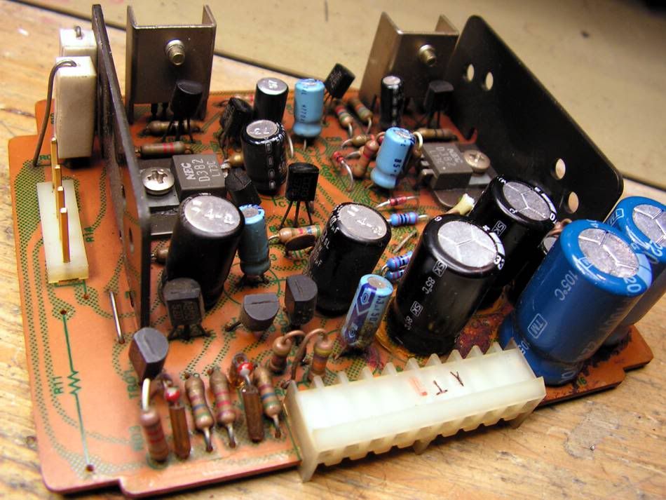
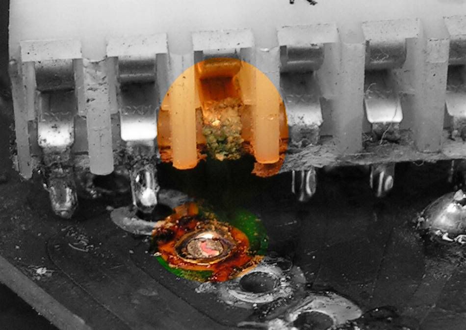
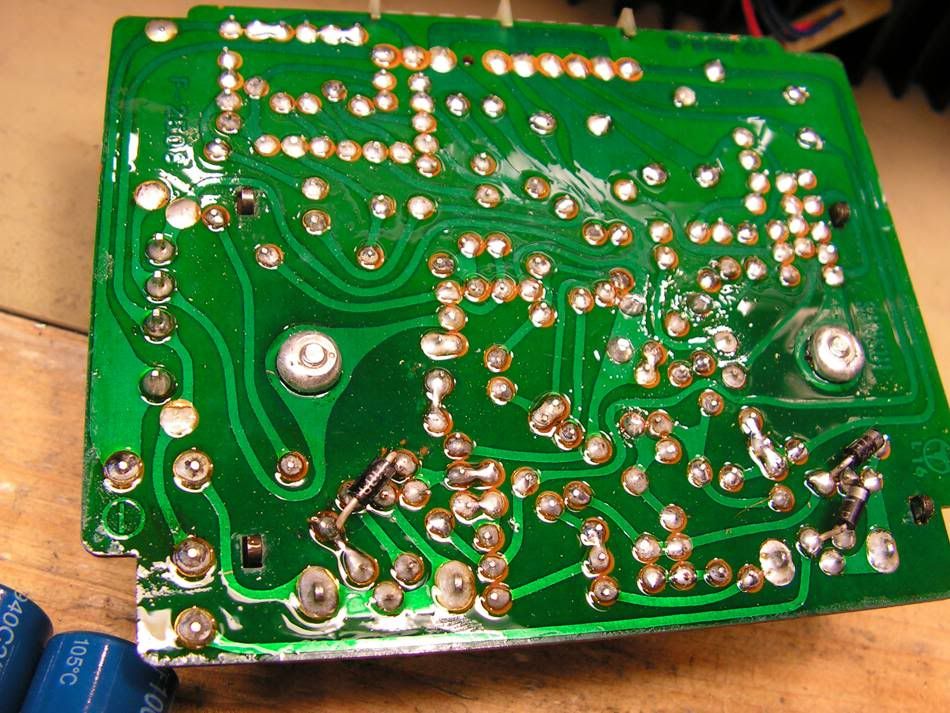
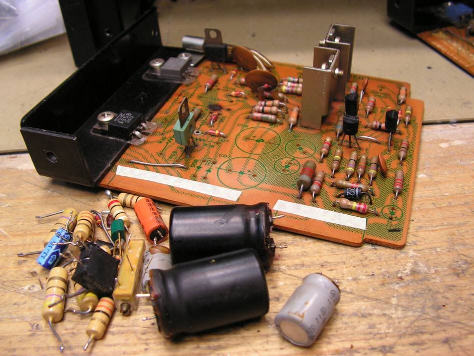
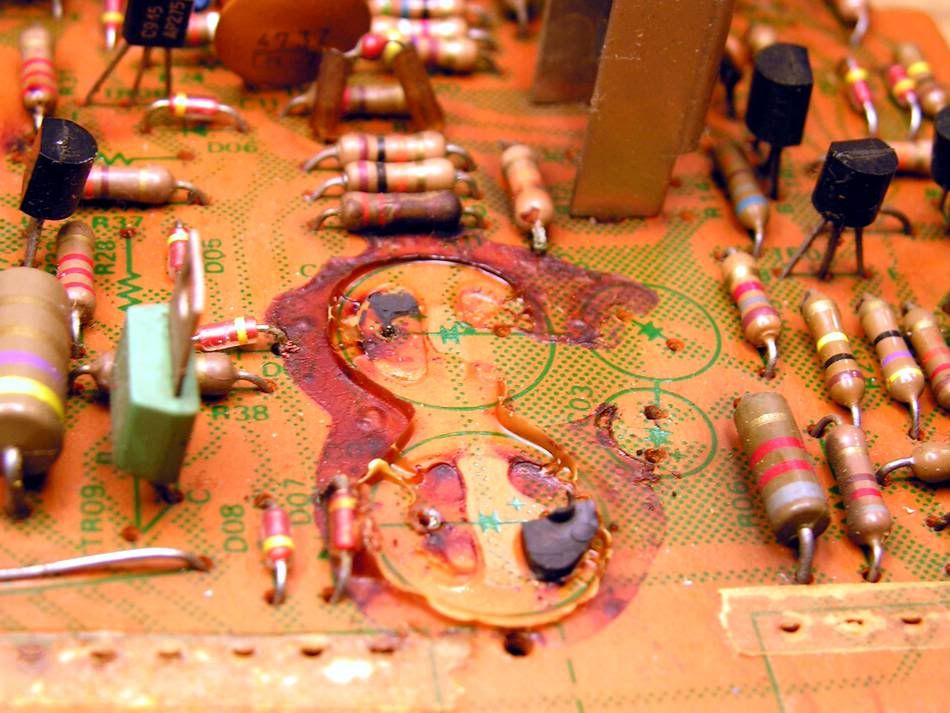
But at other side of that board, I have found some job from someone in the past, and that job was not nice
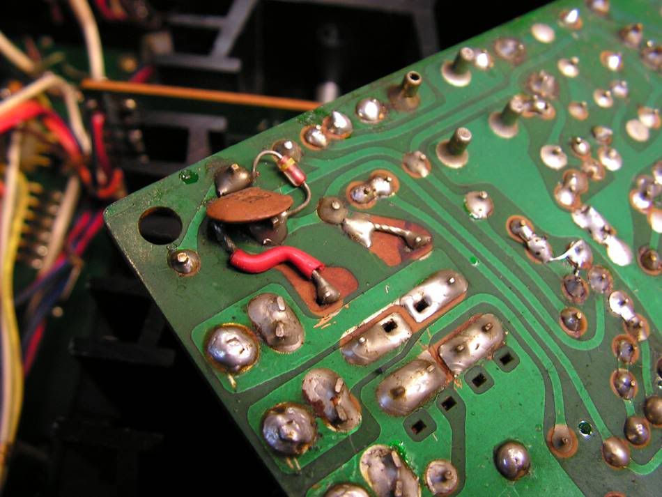
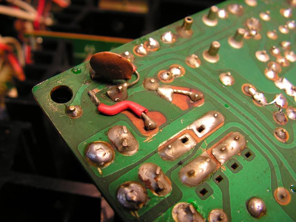
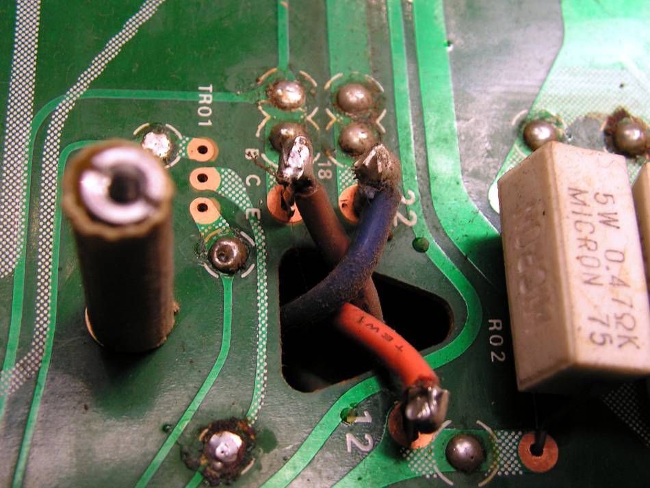
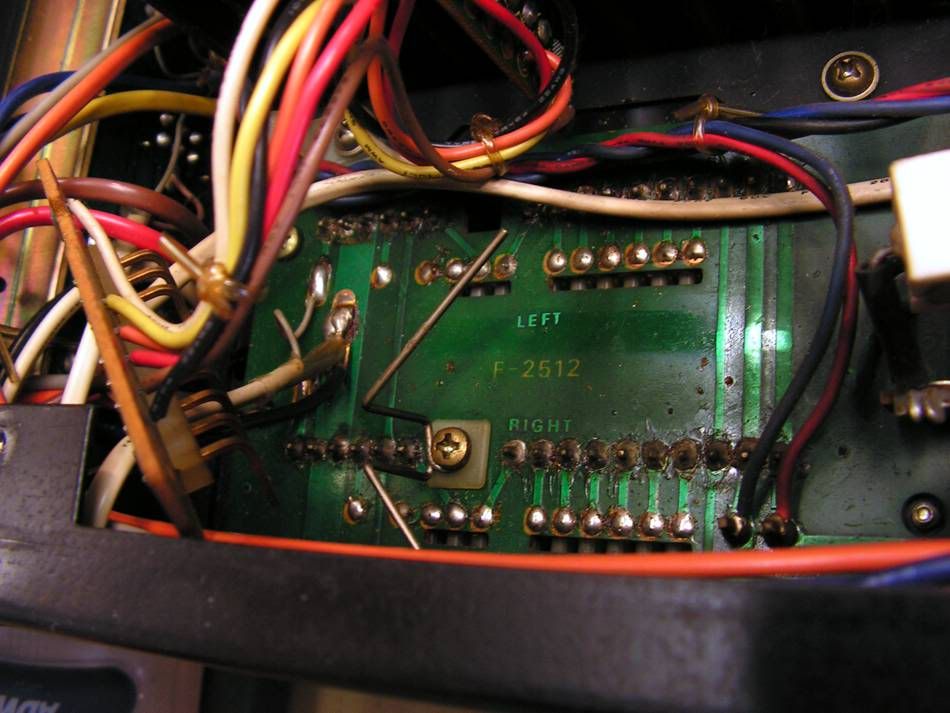
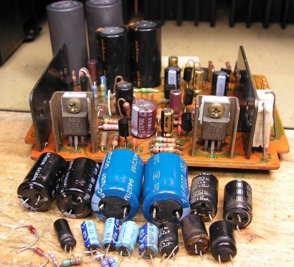
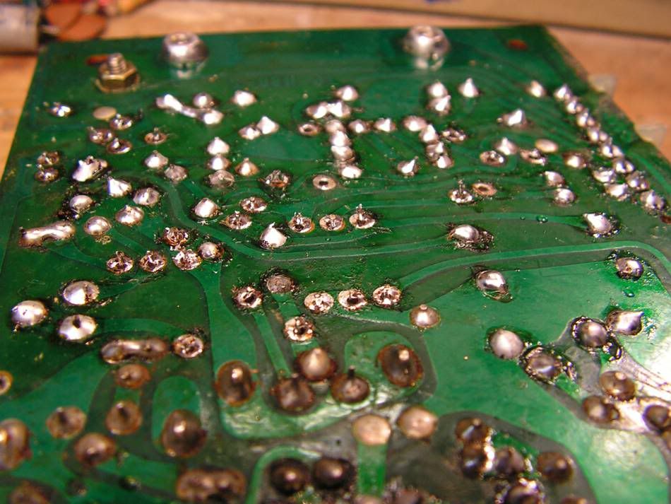
So I decided to make one "face lifting" on that board")
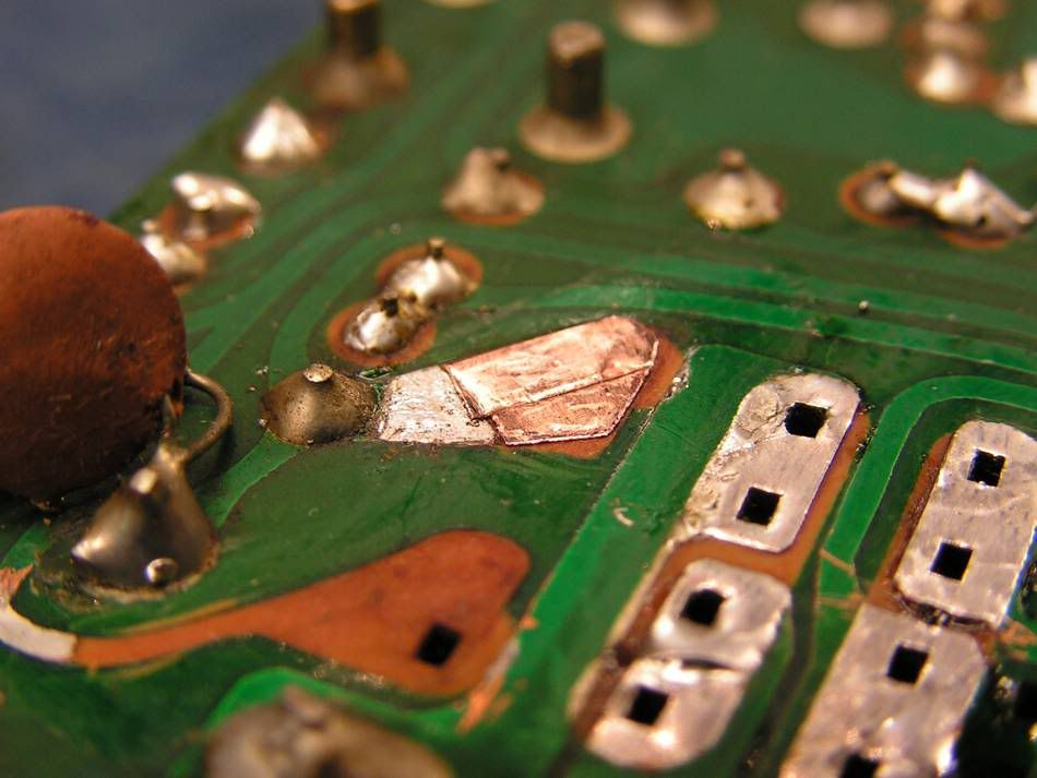
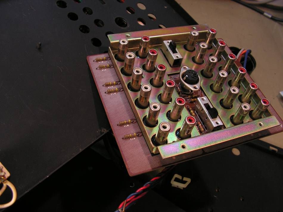
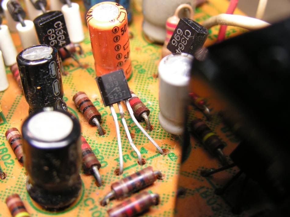
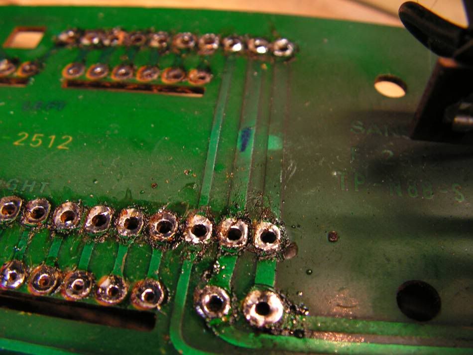
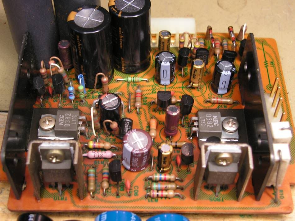
and the result is
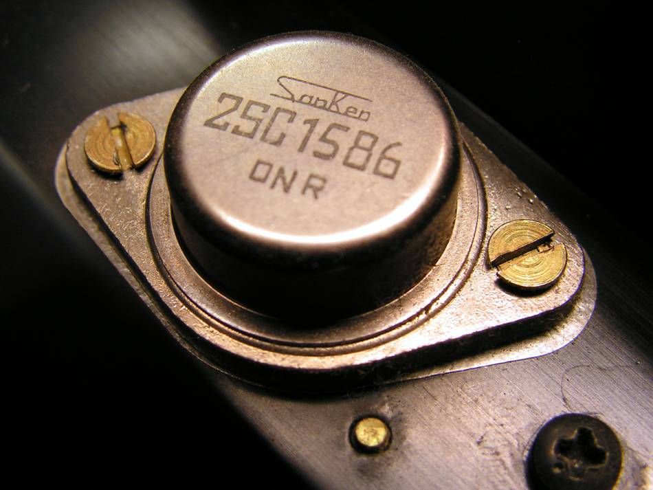
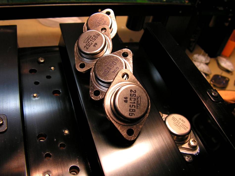
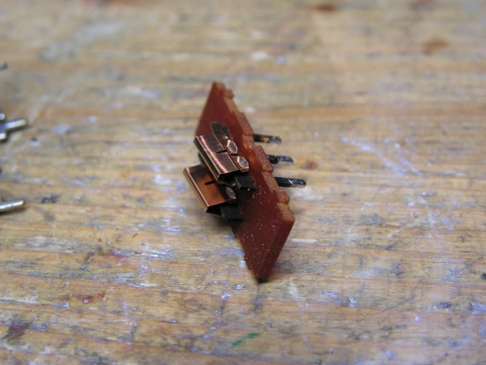
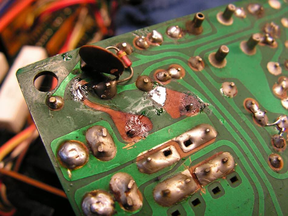
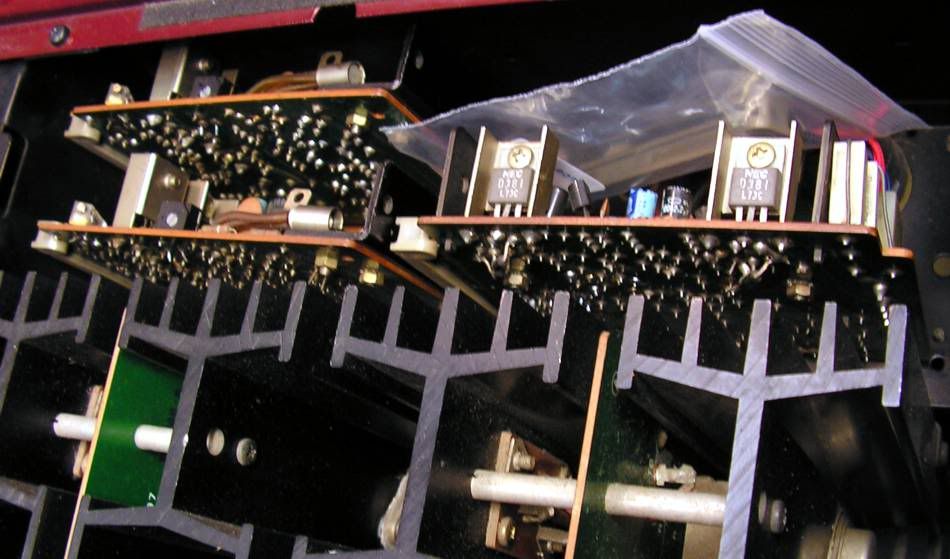
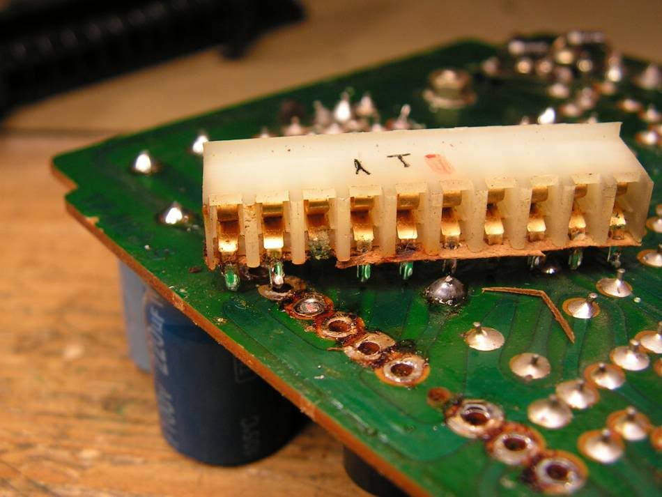
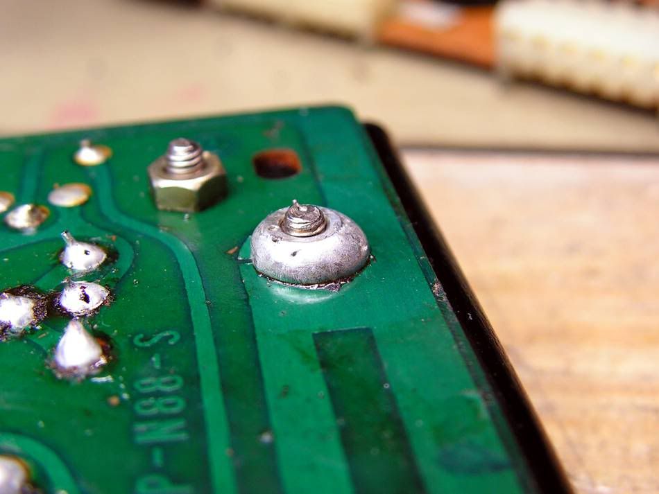
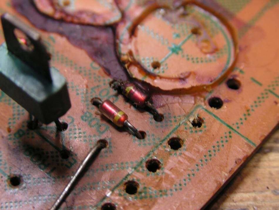
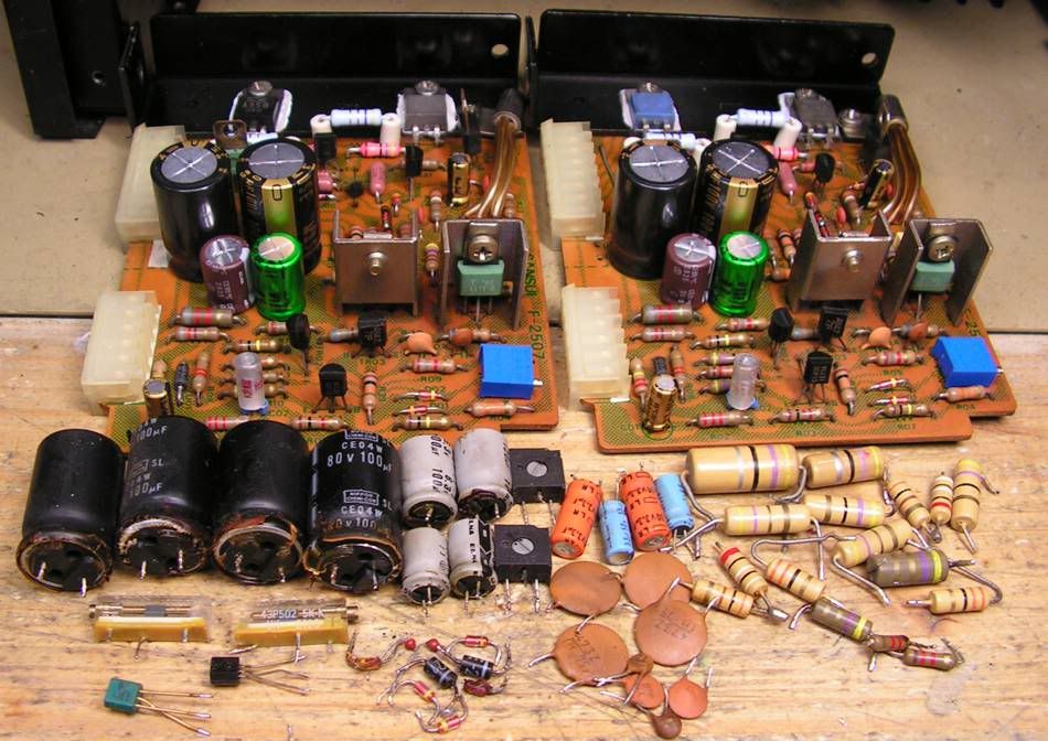
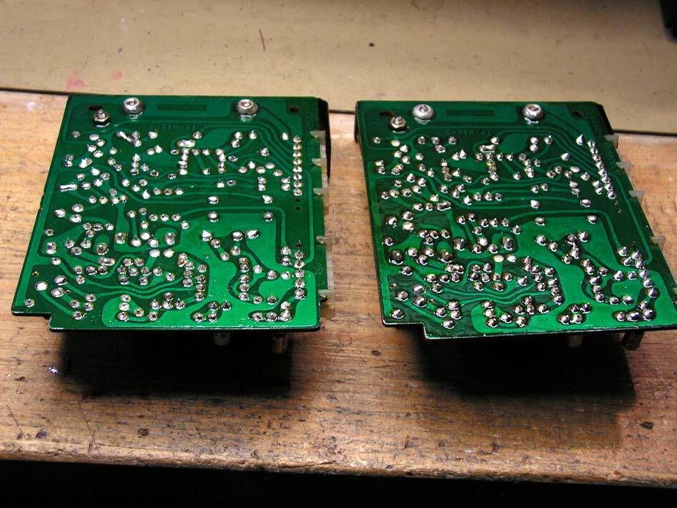
... but it was not only one problem...
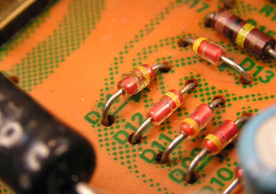
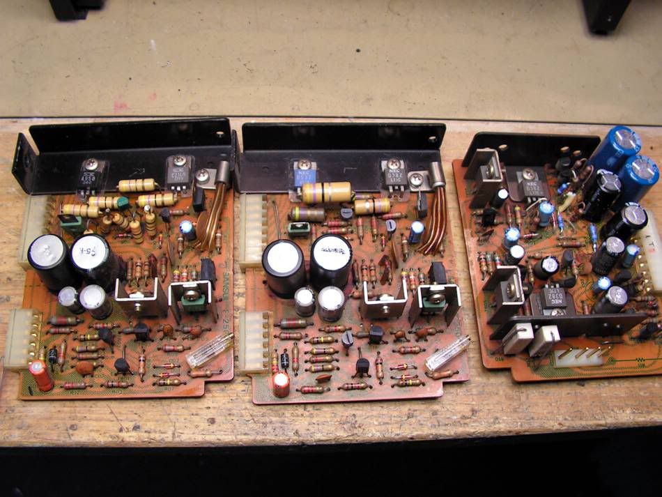
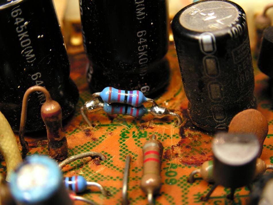
... or look at that small signal diode...
So maybe I will not finish today with posting all pictures, but tomorrow I will... so...
This is the first picture, about what amplifier I am talking here
It is really nice amplifier, but it has a problem, it stays in protection mode...
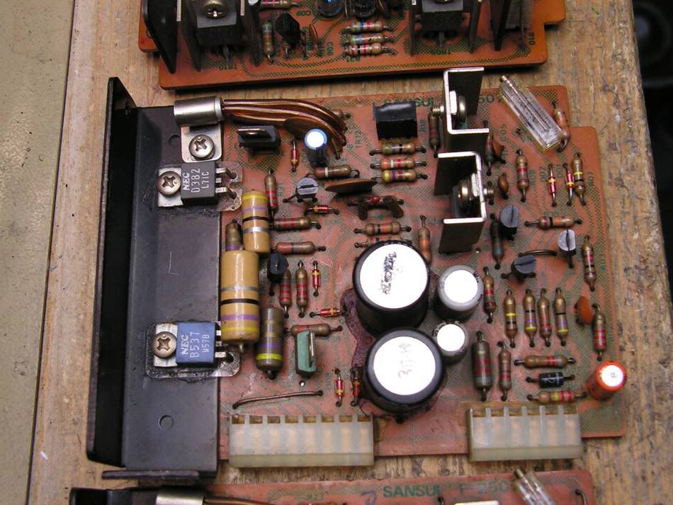
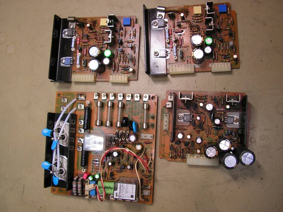
So my restoration has started with this board:
This is a board where is the main rectifier and where is protection circuit
But at other side of that board, I have found some job from someone in the past, and that job was not nice
So I decided to make one "face lifting" on that board
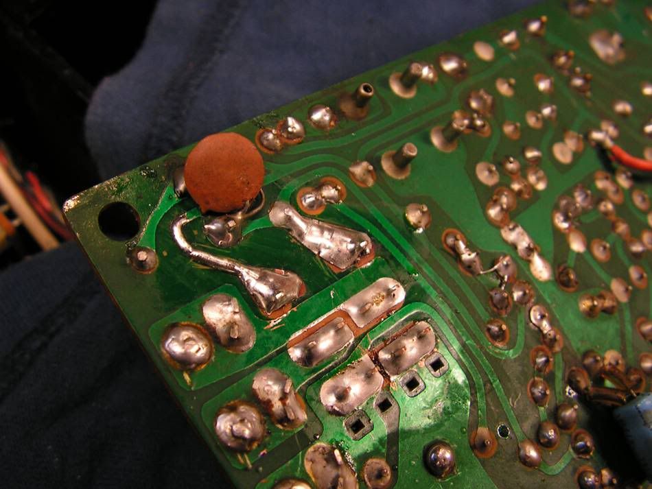
and the result is
... but it was not only one problem...
... or look at that small signal diode...

 !
!
 :ntwrthy: