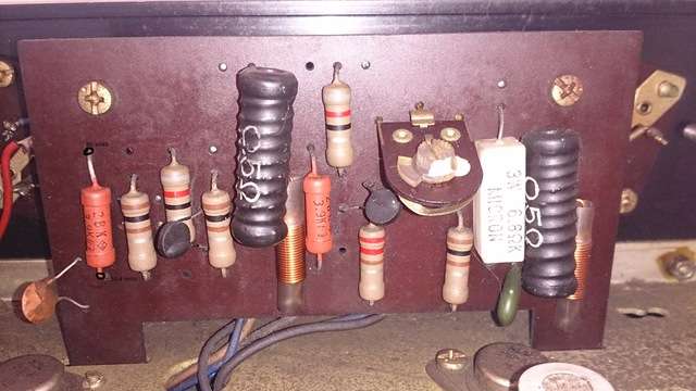
John (skippy123) is right on ! - If you don't feel comfortable measuring across the emitter resistors R853,854, or as John refers too - you only have "normal" probes - you can alternatively get the bias reading by removing the fuses F002/002 (between the two vertical driver boards) and then measure across the fuse holders - but measure for mA !! (the service manual available at hifiengine.com have descriptions on this) We also need the DC voltage on the pins as John described from the supply board 2SF-656. The SCR pot - VR901 - also located on that board could certainly be the culprit - these pots are failure prone, and if stored / operated in a humid climate for decades can become inoperative or intermittent. Here you should clean the pot by spraying a tiny amount of de-oxit onto it, and then move the pots several times from stop to stop. However, before you do that we want to make sure you leave the pot "in place" where you found it in case it was set correctly, and not the culprit. So setting you DMM to OHM, take a reading between one of the outer legs and the center. Note the resistance. After cleaning, set the pot to the same resistance by measuring on the SAME two legs.
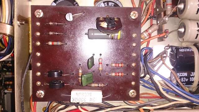
A cap coupled amp like this, have no adjustment for DC-offset as we know it from Direct coupled amps (with or without relays) - instead it has adjustment for "center voltage" or as the manual calls it - "main amp section output adjustment" - while the manual calls for an oscilloscope you can still get it done using just a DMM - we can cross that bridge later. However, with the amp on, speakers selected, idle signal and either speakers OR an 8-16 ohm load connected to the terminals you selected, you can measure the DC-offset, even if you cant adjust it. Here, in an ideal world, you should see 0mV, but will likely have something along 5-15mV. Much higher than that would indicate that your Output capacitors C825/826 are not doing their job of blocking DC, something that along the other ailments should be addressed as well.


 ...... Please tell me I am not the first one to slip up here ......