Sherwood S-8000IV - hum in phono/tape inputs

basplin

Active Member
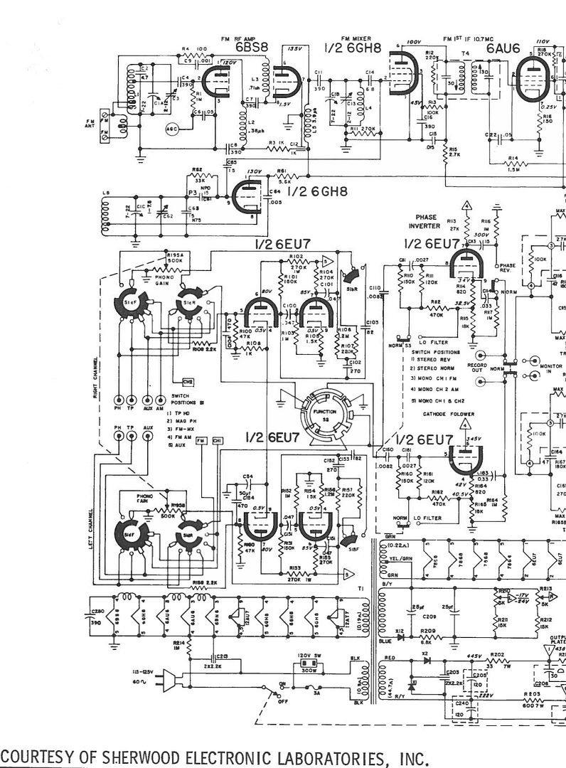
Hi all - I retrieved my Sherwood S-8000IV from the shop yesterday after 7 months there. Due to a lack of communication/completion, I decided it was time for it for come home - the tech did not finish it. He did replace several caps and put in new power tubes - EH 7868's. When I brought it to him, all inputs had some noise in them and the sound was lopsided - it came out of the right speaker more than the left speaker. The AUX section works great now. No noise, balanced sound.

There are a few things that I want to see if I can fix myself.

The FM tuner (no AM tuner on this unit) works in stereo and mono, but the sound is still not balanced in the center - it's louder on the right side and I have to turn the balance knob about halfway to the left for it to be centered. Again, this was an issue I noticed on all channels when I originally took it to this tech 7 months ago.

The second issue is a loud hum in the phono and tape inputs - and that's with nothing hooked up to them. The hum does respond to the volume, so that would mean it is a grounding issue, right? I know these inputs work as I used them regularly before taking it to this tech 7 months ago.

Any ideas as to what I could look at that could be causing these problems? Please be specific as possible - I am good with my hands and fixing things, but am still new to tube audio.

Thank you!
 
Last edited:
I have one of these and they can be a handful to fix. First, since the tape and phono share the same tube section we know the problem must be there. Swap the 6eu7's around to rule out tube problems (could be a heater to cathode short in a tube). The two on the left are the phono tubes, the two on the right are tone circuit tubes. It could also have a wire broken or not soldered on the phono gain control. They actually forgot to solder that from the factory on mine.


The radio L/R imbalance might be the 12au7, it's the final preamp for the fm radio. The power supply caps on top are shared for both channels, so we could rule those out for left/right problems. I know this receiver really, really well. I had to practically rebuild mine because it was a parts unit I got for free and was hacked up. Now it works great.

(A picture of the insides would be really helpful.)

I got the schematic for the S-8000iv if you want it. If I can still find it.


Keith
 
Hook something up to the phono input to see if the hum goes away. Its not uncommon to get that noise when its seeing an open circuit. A pair of shorting jacks would be just the thing to use here. its simply an RCA plug with the center pin connected to the outer shell.
 
As you know, the phono and tape inputs are very low level amplifier sections. They provide a lot of amplification and several things come to mind.

- If the tubes in question require a shield, is it in place around the tube? And, if it is, is it making good electrical contact with "ground"?

- Is there a shield or baffle that is around the preamplifier section? Has it been left off?

- Is there a bottom plate for the amplifier? If so, is it in place and electrically connected to "ground"?

Whilst I don't have that specific receiver, I have worked on a 5000 series amplifier at one time. And, I have a fair amount of experience with HH Scott tube amplifiers. I know for a fact that a Scott will hum if the bottom plate is left off.

As a last resort, some manufacturers suggest that grounding plugs be placed in unused inputs. One of them can easily be made by taking a male RCA plug and soldering a jumper from the center connector to the outside "ground" connection of the plug. If you make the jumper into a loop, it can be used as a handle to remove the plug.

You may have issues like H-K leakage in the tube if it has AC on the filament instead of DC, I am not sure what Sherwood used on your receiver.
Just a thought.
 
Hook something up to the phono input to see if the hum goes away. Its not uncommon to get that noise when its seeing an open circuit. A pair of shorting jacks would be just the thing to use here. its simply an RCA plug with the center pin connected to the outer shell.

OOPS! I was still typing as "Gadget" was posting this response. (The AK site has very, very slow response so I often start typing only to find out that someone else said the same thing, a few minutes earlier, sorry!)
 
Thanks for the responses, guys. So I went through and tried a few things.

I swapped around the 2 pairs of 6eu7's nearest the front of the unit and made sure the tube shields were on securely. No dice, still a hum. I should mention that it is only coming from one side, not both. It looks as if all the shields are present. There aren't any on the two middle 6eu7's, but those didn't have shields when I got it and I didn't have any issues with hum then.

I don't have any shorting jacks, but I hooked up a record player to the phono input - also did not get rid of the hum. I can make some shorting jacks but thought I'd try this first. Should I make some?

One thing I do not have is the bottom cover - my tech lost it (!) but I managed to find another one on ebay, so it should be here next week. Perhaps the bottom cover is a ground for the tape and phono inputs, but not the AUX and FM? (the aux and fm work fine).

kvflyer - can you elaborate more on the H-K leakage and what tube that would correspond to? I do not know how much my tech checked these smaller tubes, so that could be the case! Also, I believe that this S-8000 had the same amplifier section as the S-5500!

Keith - I'm impressed that you've rebuilt one of these before! These look like a major PITA to work on, and some of the parts are pretty hard to come by, yeah? I looked at the knob for the phono gain and as far as I could tell, the connections are intact. Is there a specific spot I should look at to check the ground?

I did notice that one side of the power tube shield is not soldered to the chassis, but the other is. I pressed down the loose side and the hum did not go away.
 
Last edited:
Attached are the pictures of the top and bottom of the unit
 

Attachments

  • Top.jpg
    Top.jpg
    83.3 KB · Views: 79
  • bottom.jpg
    bottom.jpg
    121.9 KB · Views: 88
I forgot to add:

kvflyer: I do not think there is a baffle around the preamp section. If there was, it was gone before I got it and I was able to run it alright without it.

Keith - I would love a copy of the schematic if you can find it, thanks! It may help me figure this out.
 
Last edited:
In looking closely at the bottom image, next to the power transformer it appears thereis a broken or disconnected red wire. There also appears to be a couple areas where insualtion has been melted. I would check lead dress and make usre those 2 wirewound pots are securely mounted (they are probably okay, but that one with an electrolytic hanging on it might be a problem later on- it looks like an old stock unit from the 70's or 80's.

If you have not done so, you might try rocking the tubes in their sockets with the unit in operation- if a pin or socket contact is corroded, this may clear that up temporarily.
 
Schematic, 3 pages

S-8000%20IV_Sherwood_zpsbelo9iaa.jpg


S-8000%20IV_Sherwood2_zpshnjttbfe.jpg


S-8000%20IV_Sherwood3_zpswcrekkwp.jpg
 
I checked the red wires around the transformer and everything looks like it is still securely attached. Which wire wound pots in particular did you notice to be problematic, Trio?

I checked the tubes with the unit on, and everything seems to be secure. Would it be worth cleaning the tube sockets?

One thing I just discovered - the tape monitor channel works. When I flip it to the monitor, the hum goes away and I get great sound, a la the AUX channel.
 
In looking at the image as you have it posted. You have a number of electrolytics on the left side about midway up- If any of those are not new (the bluish one looks like old stock) Replace them. If it were mine- all the electrolytics would just be replaced based on the appearance of what is there right now. I would not trust them. You have one black, one blue, one orange, one silver right in that small area. The blue/purplish one looks to be connected to one of the wirewound pots rivited to the chassis- it appears to be an old stock from the 1970's to 1980's. That silver one is a low voltage rating type and original, but if it is failing you would have different symptoms.

And looking at what you have there in general is a problem. All the original electrolytics are still in circuit- this poses a multitude of potential problems including fire or catastrophic failure of some near unobtanium parts. The original terminal lead of the original electrolytics must be kept out of the circuit or it defeats the purpose of the replacement in some cases. If the new cap is reasonably secure in position by the other lead, you can carefully manuever a heavy wire cutter down and clip the original terminal lead of the old capacitor near the body of the original capacitor.

But as for the imbalance on the tuning section- if you have a scope or a reasonable analog AC voltmeter, locate the 12AU7 "Channels 1&2 Audio Amp" tube. Off of pin1 and pin 6, there is a capacitor with a resistor in series with it that tie to ground/chassis. At the point between the resistor and capacitor, you should be able to measure an AC voltage. If you are tuned to a station with voice and not music, you should see the same voltage at those 2 points with one lead of the test meter tied to the chassis. If you have an oscilloscope, you should see the same relative signal peak votlages. If voltages are the same, then the issue of imbalance is between that point and the 6EU7's after the selector switch. it is possible one of the switch contacts is dirtier than the other or even damaged.

If the voltages are not the same, check the tubes in the FM section, that specific 12AU7 should be balanced. If the merit varies more than 10%, this might be all of the problem . If the voltages are the same, there is probably a dirty switch contact or cold solder joint.

Make a couple of shorting plugs as mentioned previous, and see if those tone down the Phono section. When they are not loaded, they can pick up random noise or generate their own. See if that quiets it. If it does not quiet things down, there may be a bad solder joint or loose wire.

Now, the wire I noted, in the image it looks like it may be broken off, it is in close proximity to the 6.8K resistor (Blue Grey Red) just left of the power transformer near a rectifier. While it may just be how the insulation melted back when the wire was soldered, it looks like it is just hanging there when you zoom in on the image.

With the schematic above from Repair Guy, you will learn a lot about fixing this amp by the time you are done.
 
Yes! This is very helpful.

I *think* the black, orange, and the blue/purple-ish one are new caps that were just replaced. I will call the tech and verify this. They look much newer than other components inside. The bluish/purplish one might be NOS - is that an issue? I'll ask about that one. The silver one is actually a wound coil of wire, which would make it a resistor?

The tech I had taken this to had issues finding replacement caps due to the very tight space in this unit. Would you happen to know if any of these caps you mention are particularly small for their values (I can look), and if so, do you know of a vendor I could get them from? Repair Guy/Keith, did you have issues with very many of the cap sizes when you rebuilt yours?

"The original terminal lead of the original electrolytics must be kept out of the circuit or it defeats the purpose of the replacement in some cases." - Why is that? Is the wire different? Maybe I am misunderstanding what you're saying...

I have a friend that owns some testing gear, so I will go through and test these things with a meter this week and see what I find.

Thanks!
 
If the original capacitor has shorted internally- the short remains in the circuit until that termination is cut.

If that one item is a coil of wire it is a choke/inductor- though I have seen a few instances of a resistor or even a capacitor that were wrapped in wire.

Most of the high ripple current type electrolytics (a sorting criteria I use for electrolytics available in Digikey's sort table) are amller in physical size and will fit under the chassis. When I replaced the caps in my Sherwood S5000II that was a bit more cramped for space than yours is and I ended up stuffing caps into the one that sits at an angle in the clamp of the S5000II. I did not want to but had to.

Unless the lighting you are using adds a purple tint, I still think that one may be an old stock capacitor. A few of the electrolytics under the chassis look to have been added over the years. If it were mine- all the electrolytics would be replaced just to make sure- with new stock caps following the original schematic, not what may have been added in over the years.
 
So you're saying the short can happen in the terminal lead as well?

Yup - sure enough, there is a capacitor wrapped inside that wire. Are there capacitors still made with wire wrapped around them?

I would love to get this amp back to factory/schematic spec eventually - first I need to learn how to read a schematic! I can't seem to find where the purple capacitor is - can you point me in the right direction?

While I was looking across the bottom of the unit, I found a wire that isn't attached to anything. Attached is a clearer picture of the bottom. The wire in question is just to the right of the pair of green caps near our purple capacitor friend. It's a short black wire that got cut to about an inch in length, not attached to anything. I also tried to find this on the schematic and had no luck. Is this an issue?

Thanks!
 

Attachments

  • photo-37.jpg
    photo-37.jpg
    137.2 KB · Views: 49
Last edited:
Yes! This is very helpful.

I *think* the black, orange, and the blue/purple-ish one are new caps that were just replaced. I will call the tech and verify this. They look much newer than other components inside. The bluish/purplish one might be NOS - is that an issue? I'll ask about that one. The silver one is actually a wound coil of wire, which would make it a resistor?

The tech I had taken this to had issues finding replacement caps due to the very tight space in this unit. Would you happen to know if any of these caps you mention are particularly small for their values (I can look), and if so, do you know of a vendor I could get them from? Repair Guy/Keith, did you have issues with very many of the cap sizes when you rebuilt yours?

"The original terminal lead of the original electrolytics must be kept out of the circuit or it defeats the purpose of the replacement in some cases." - Why is that? Is the wire different? Maybe I am misunderstanding what you're saying...

I have a friend that owns some testing gear, so I will go through and test these things with a meter this week and see what I find.

Thanks!


When I changed all the caps in mine I soon found out there was not enough room under the chassis. I installed them on top.

I cut the cans off, leaving the terminal base, then simply drilled really small holes in the base of each cap for the leads to go through. Then you can solder them easily. Not as pretty as the original cans, but I didn't have the money to buy quad caps. Finished that off by hot gluing the caps so they don't move. Turned out really good, and not as messy as putting in terminal strips. I usually install them under the chassis, but this was a special case. So many caps, so little space. Just make sure there's no exposed voltage!

Keith

IMG_20150614_192102_zps71htkyzo.jpg


IMG_20150614_192137_zpscy1jnxwj.jpg


IMG_20150614_192206_zpsdhwqlcmi.jpg


IMG_20150614_192226_zpswrdc2ycn.jpg
 
I put the tops back on my cans with aluminum duct tape. I used brake cleaner to remove the printing from the tape so it blends in better. I can still peel it back off and get to the caps if I need to tho
 
The black wire may belong on the loop it appears to be resting close to. If it looks like a strand of wire is in the loop, if there is, try connecting that black wire at that location.

With a little less contrast and a different angle, that red wire I saw appears to just be insulation that melted when it was soldered.

The amp should have been completely recapped just out of hand. It appears that all the newer caps on the bottom of the chassis are just tied in parallel to the old caps- which is a safety issue.

While it will be a chore to grub out the contents of the old capacitors, in the long run it does make for a tidier appearance. As far as trying to reuse the newer caps- Don't. Not worth the headache.

I will say this- whoever worked on the amp previously- it makes my worst soldering look a whole lot better. I know this does not build confidence in the previous work, but I really don't see anything in the previous work to be proud of.
 
It appears that the end of the black wire isn't near any terminal - I've attached a picture showing where it is a little better. Could this be causing the hum in the phono/tape inputs?

I just received the bottom cover today. After putting it on, the hum is still there.

Does anybody have a parts list for this? I think this is something that is found in the original manual. That could help as to ordering the correct capacitors. Repair guy, what did you use?

Trio - as far as capacitors that need replacing, you are saying that ALL capacitors need to get replaced, and not just the few electrolytics?

Thanks!
 

Attachments

  • photo(1).jpg
    photo(1).jpg
    107.4 KB · Views: 41
Last edited:
It appears that the black wire isn't near any terminal - I've attached a picture showing where it is a little better. Could this be causing the hum in the phono/tape inputs?

I just received the bottom cover today. After putting it on, the hum is still there.

Does anybody have a parts list for this? I think this is something that is found in the original manual. That could help as to ordering the correct capacitors. Repair guy, what did you use?

Trio - as far as capacitors that need replacing, you are saying that ALL capacitors need to get replaced, and not just the few electrolytics?

Just the electrolytics- that includes those electrolytics that were soldered underneath because those are of questionable age and are currently soldered in parallel with the original electrolytic can caps. (this includes a number of black, orange and the bluish purple capacitors- these all have the aluminum body with a shrink plastic covering and are values larger than 1 microfarad.)

Put a different way- if it is 1 microfarad or larger- replace it. Use the schematic as a guide to how many and confirm with the data on the large can caps- there are usually on the cardboard sleeve or stamped into the body of the capacitor- these will tell you of what capacitance values you need, and the working voltages.

That black wire looks to be just a stub from aprevious repair or attempted modification. However a missing ground connection will lead to noise.

Note too- there are a couple of original elecrolytics with a translucent orange/red tint to the plastic covering- replace these as well. The capacitors smaller than 1 microfarad are high quality caps and are best left alone.

If the hum is 120 hz, chances are that it will disappear once the electrolytics are straightened out.
 
Last edited:
Back
Top Bottom