

Thumper
Well-Known Member
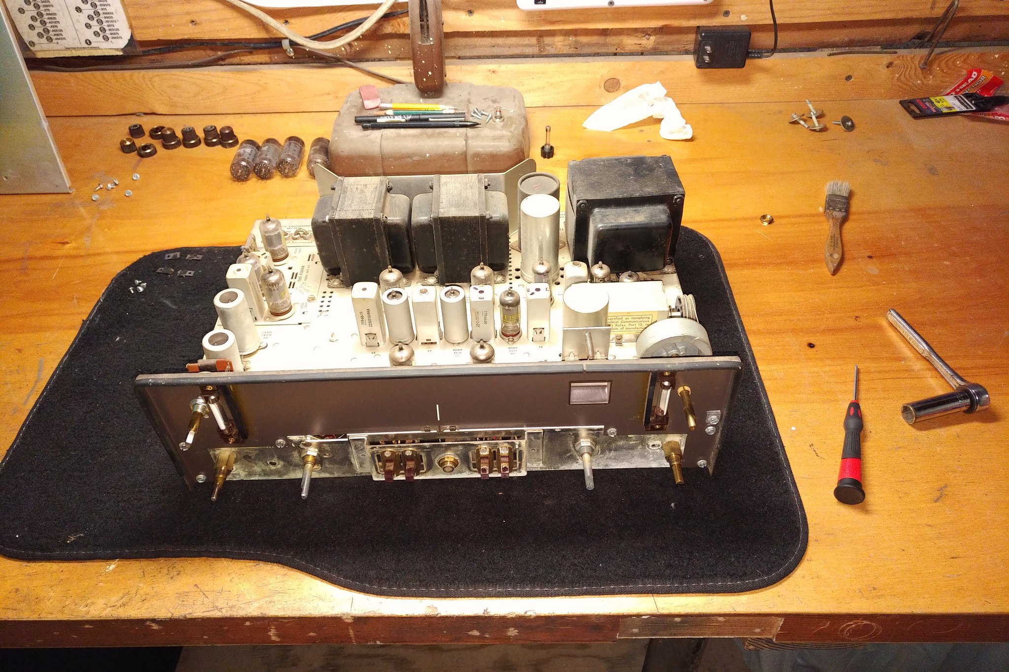
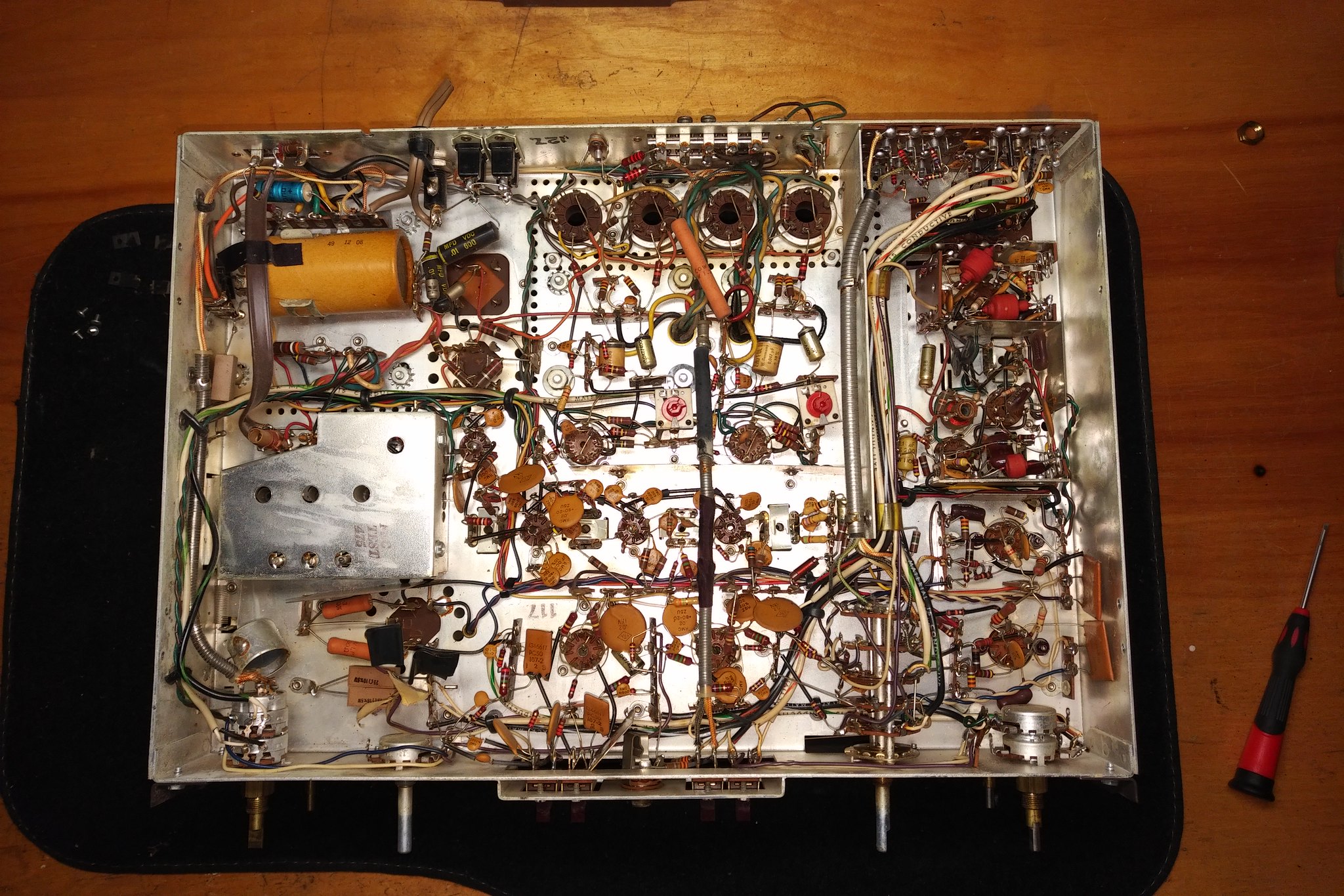
Picked this up yesterday locally. S/N 66,xxx. Paid a good amount for it but I think it was fair, especially considering that I've now got it mostly apart and realized that it's almost completely original and untouched.
 2017-06-27_12-01-10 by rickenbacker_man, on Flickr
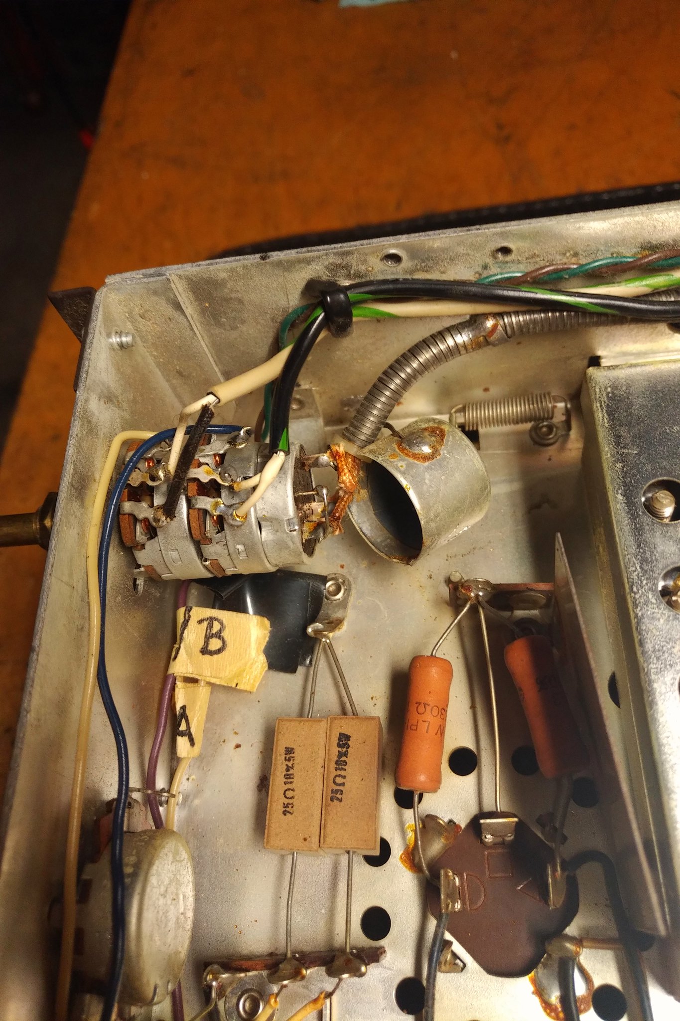
The only deviations from stock that I see - there are two wires (one white one purple) that come off of the loudness switch that have been disconnected and have electrical tape on the end. Also, the cover on the back of the on/off switch is just kind of dangling there. Not sure if it was taken off or if it fell off. Maybe this pot and switch has been replaced at some time? Did the original pot have a loudness tap? That would explain the loose wires. I didn't take any close up shots yet but I can get some later.
 IMG_20170626_2300117 by rickenbacker_man, on Flickr
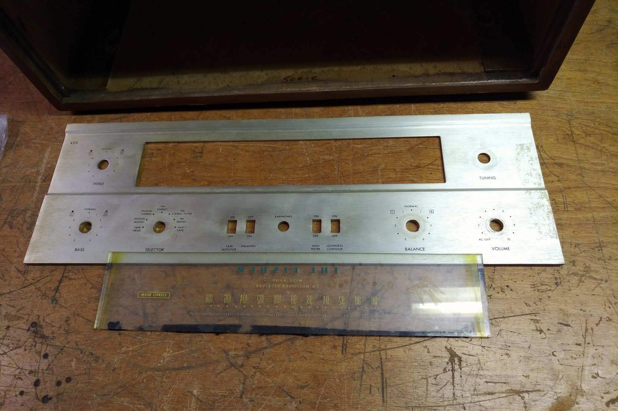
Hoping the front panel and glass clean up nice, I haven't tried to clean them yet. The thing is DIRTY.
 2017-06-27_12-03-45 by rickenbacker_man, on Flickr
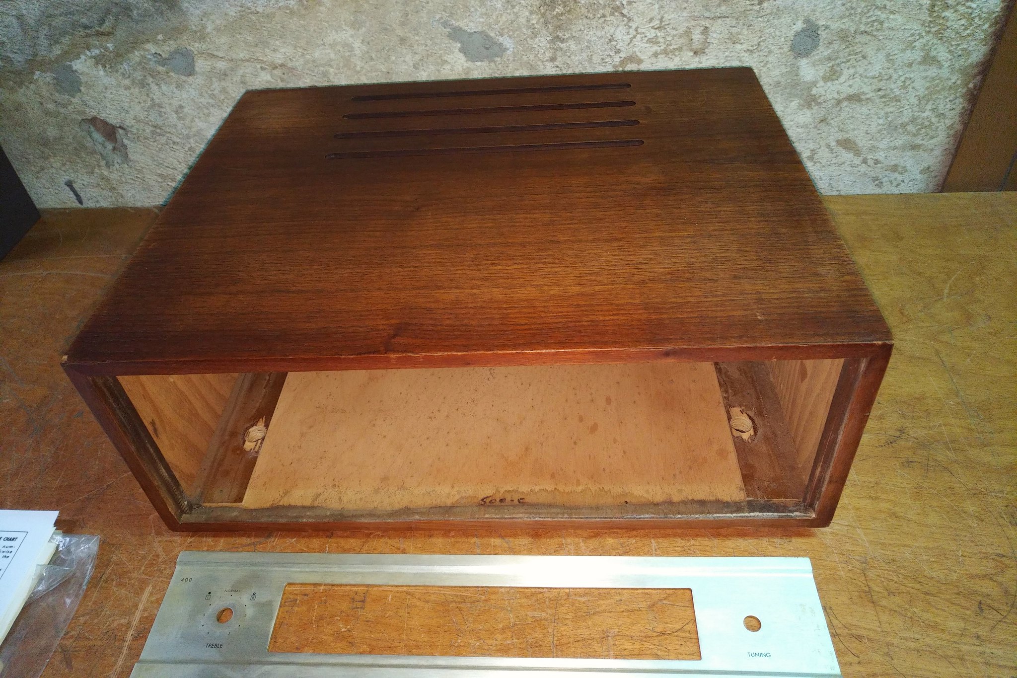
Is this a legit Fisher case? I've seen another 400/500 in the same one, but it doesn't look like the usual ones with the metal screen on the upper back.
 2017-06-27_12-04-26 by rickenbacker_man, on Flickr
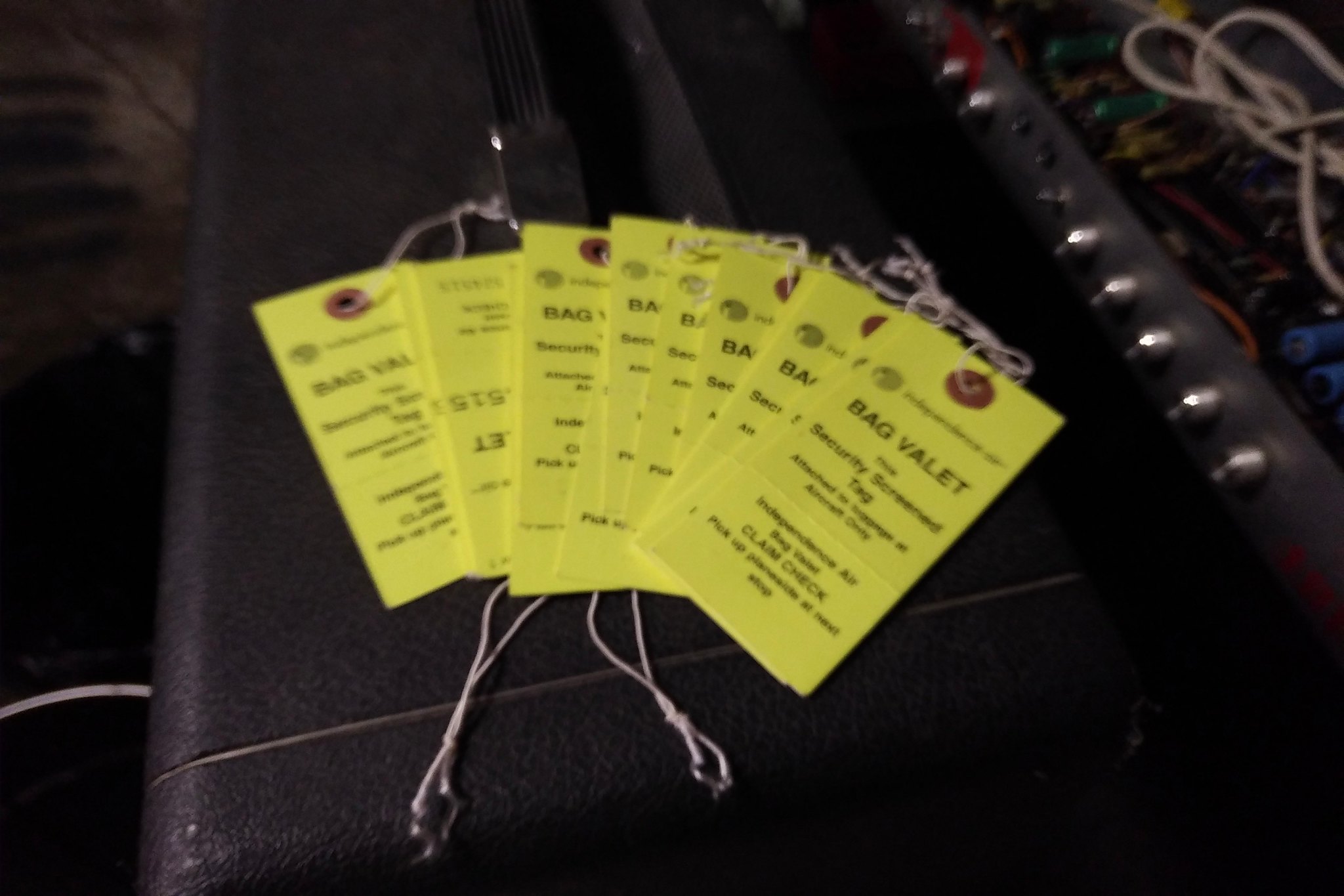
The thing also had all these valet tags packed inside, kind of funny...
 2017-06-27_12-05-47 by rickenbacker_man, on Flickr
All of the small tubes are Fisher branded, power tubes are GE's. I tested them on my B&K 747B, two are at about 75% and two are at about 25%. I may snag another used pair off ebay and do the IBAM board. I will also be contacting Jim McShane today to inquire about a full rebuild kit.
Also - the bonehead seller had turned it on. I assume without speakers connected. He took pictures and I guess the positive is that it powered up and didn't release the magic smoke, but one of the pics showed one of the power tubes redplating.
Good fun!
2017-06-27_12-01-10 by rickenbacker_man, on FlickrThe only deviations from stock that I see - there are two wires (one white one purple) that come off of the loudness switch that have been disconnected and have electrical tape on the end. Also, the cover on the back of the on/off switch is just kind of dangling there. Not sure if it was taken off or if it fell off. Maybe this pot and switch has been replaced at some time? Did the original pot have a loudness tap? That would explain the loose wires. I didn't take any close up shots yet but I can get some later.
IMG_20170626_2300117 by rickenbacker_man, on FlickrHoping the front panel and glass clean up nice, I haven't tried to clean them yet. The thing is DIRTY.
2017-06-27_12-03-45 by rickenbacker_man, on FlickrIs this a legit Fisher case? I've seen another 400/500 in the same one, but it doesn't look like the usual ones with the metal screen on the upper back.
2017-06-27_12-04-26 by rickenbacker_man, on FlickrThe thing also had all these valet tags packed inside, kind of funny...
2017-06-27_12-05-47 by rickenbacker_man, on FlickrAll of the small tubes are Fisher branded, power tubes are GE's. I tested them on my B&K 747B, two are at about 75% and two are at about 25%. I may snag another used pair off ebay and do the IBAM board. I will also be contacting Jim McShane today to inquire about a full rebuild kit.
Also - the bonehead seller had turned it on. I assume without speakers connected. He took pictures and I guess the positive is that it powered up and didn't release the magic smoke, but one of the pics showed one of the power tubes redplating.
Good fun!
 2017-06-30_12-28-44
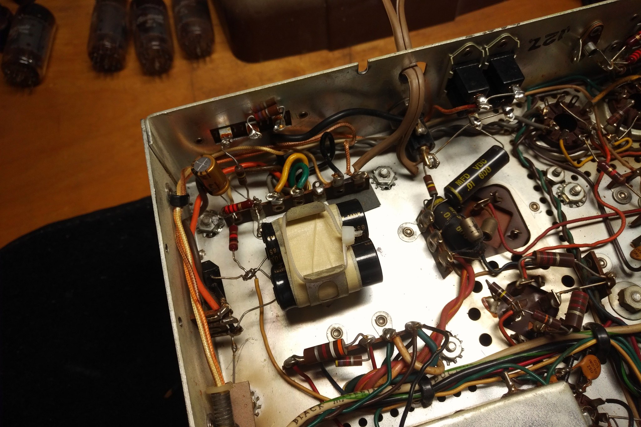 2017-07-02_12-38-55
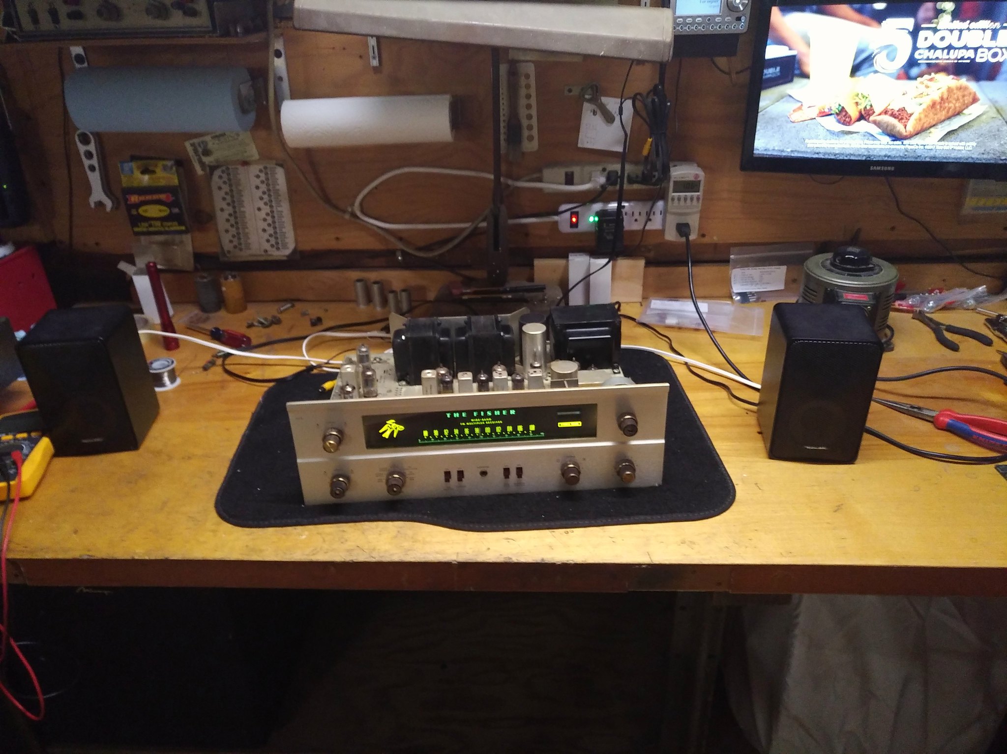 2017-07-07_10-49-20
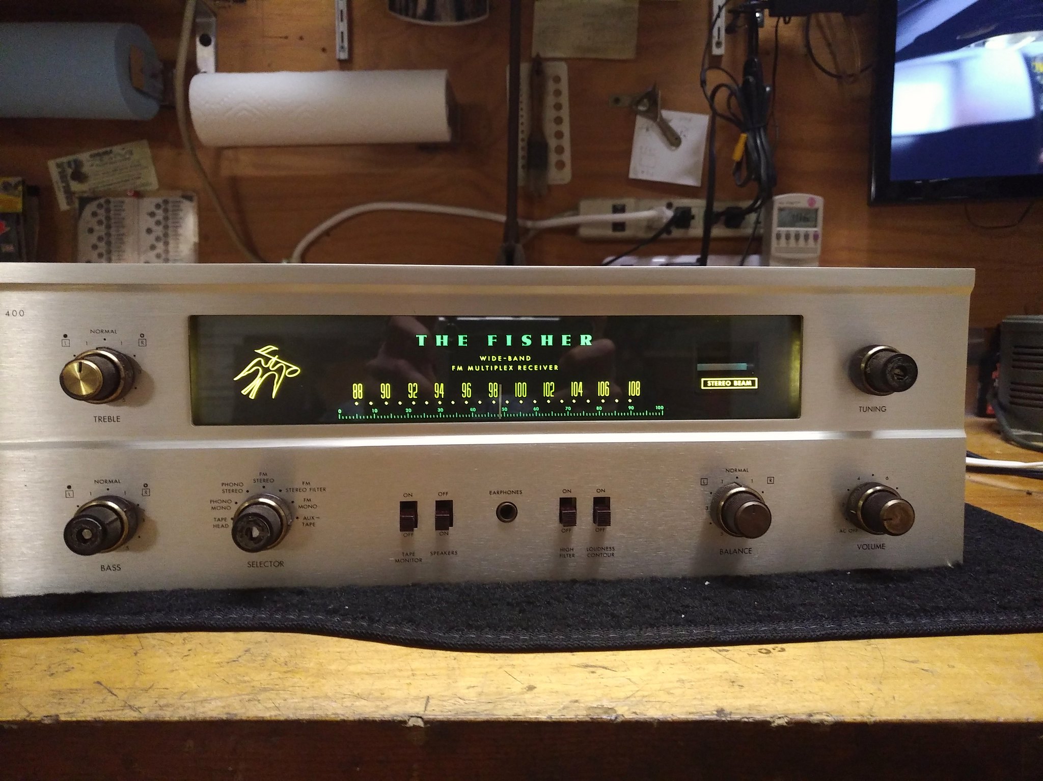 2017-07-07_10-49-54
 2017-07-17_12-02-03