

Dunno why I never noticed this before...
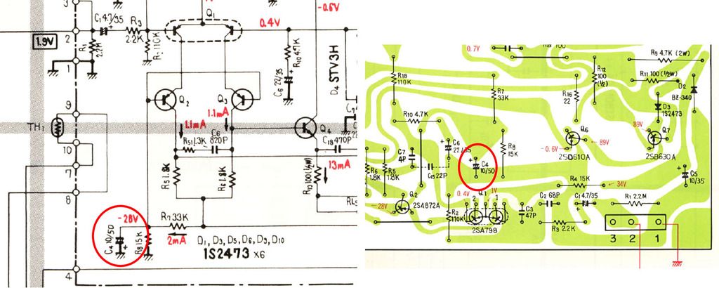
Errors like this are common...usually either the foil pattern in the service manual or the schematic is wrong, but the silkscreen on the actual PC board is generally OK. But you can see that the positive lead of C4 must be tied to ground in order to avoid reverse-biasing the cap.
Had a Spec 2 here that had been 'rebuilt', but as the protection let go and the bias interrupt relay closed, the relays would all open and close again very quickly, making a hell of a racket. Looking at the board, I could see that the last guy had replaced C4 with a 10µf 100V cap (which was bulged and swollen), perhaps in an effort to cure the issue. I hung the meter at the junction of R7 and R8 and measured -7V. Not good. Then I could see that the cap was installed just like the foil diagram in the manual, and the silkscreen on the PC board also is wrong, prompting the cap to be installed with the negative lead tied to ground.
Popped the boards out, swapped the two C4's out with new caps, installed so that the positive lead is now going to ground (reversed from what the PC board shows), and now have -27V at the junction of R7 and R8.
Needless to say, this cured the slap-happy relays. So if you're working on a Spec 2, check this. This specific unit looks to be an early one, and since it was partially recapped before I got it on the bench, I can't say if the original cap was installed properly oriented or not, but I can't imagine that Pioneer got it wrong regardless of the PC board marking.


