

You are using an out of date browser. It may not display this or other websites correctly.
You should upgrade or use an alternative browser.
You should upgrade or use an alternative browser.
SPEC 2 Score!
- Thread starter rhodus
- Start date
ThanksKSA733C is the same pin out as 2SA733
Best of luck with a pretty sweet amplifier.Thanks

I need advice on setting the limiters. I have a cheap pc based oscilloscope but no audio generator. Any suggestions? I do have two 8 ohm 300w dummy load resistors.Check this thread out if you haven't already.
http://audiokarma.org/forums/index.php?threads/pioneer-spec-2-restoration-help.148523/page-6
The thread also discusses the R1 and R2 relay replacement options.
If you haven't read the correct C4 cap placement EW noticed. Read this.
http://audiokarma.org/forums/index.php?threads/spec-2-errorr.677774/
On those notes:
One of the final amp adjustments require setting the limiters.
Are you set up for adjusting the limiters?
Perhaps and App on your smart phone.I'd use and audio signal generator myself.no audio generator. Any suggestions?
http://audiokarma.org/forums/index.php?threads/affordable-test-equipment.220238/#post-2623784
I used one of these sometime ago.
https://www.ebay.com/itm/Assembled-...167386?hash=item2a6ab97c9a:g:HkgAAOSwanRXh71p
It requires a +-15v power supply.
There are cheaper ones in that category.
The equipment for this particular procedure doesn't have to be top notch.
Other than the Sig Gen you have what you need.
https://www.ebay.com/itm/Assembled-...167386?hash=item2a6ab97c9a:g:HkgAAOSwanRXh71p
It requires a +-15v power supply.
There are cheaper ones in that category.
The equipment for this particular procedure doesn't have to be top notch.
Other than the Sig Gen you have what you need.
xXColdShotXx
Active Member
I used one of these sometime ago.
https://www.ebay.com/itm/Assembled-...167386?hash=item2a6ab97c9a:g:HkgAAOSwanRXh71p
It requires a +-15v power supply.
There are cheaper ones in that category.
The equipment for this particular procedure doesn't have to be top notch.
Other than the Sig Gen you have what you need.
What's the lowest and highest voltage that can be used with that signal generator? I have 12v, 24v and 30v power packs.
xXColdShotXx
Active Member
+-15 volts input supply. 12v will work
Output 7 volts.
Ok, thanks very much. Got one of those on the way you posted a link to. I've got a 4 ohm 300w load, tektronix 2225 oscilloscope and a true rms dmm to set the spec 2 limiters.
I read in this post you need 30v for the spec 2 input, will the bay signal generator be enough if it only puts out 7v?
Last edited:
mV's from the SG into the Spec amp inputs, equal many AC volts out.
With the SG gain turned down, I'll run the gain controls up to 3/4 or so.
AC volt meter that can read in RMS, Dummy Load and the scope connected to the speaker outs or equivalent connections. Even though its kind of a temporary test as in, you don't do this all the time. It's wise to set the connections up so its not confusing and you don't short anything out.
One channel at a time.
Switch on the amp and let it warm up a bit.
Dial up the gain on the SG a tad and look for the trace on the scope. Monitor the voltage and get the scope to present that nice trace coming out of the freshly restored amp.
Follow the service manual for the results and adjustments.
Note:
Bone up on the procedure in your head before you attempt the adjustments. You can play with the procedure at first by keeping the gain settings in the low volt area, like under 8VAC from the speaker terminals. Watch the scope trace increase while adjusting the SG gain. You will have to set the oscilloscope graticule per division lower as you increase the gain up to the limiting spec.
Once you get set up, and get to doing, you'll catch on to the process.
When you decide to set the limits, do it quickly. The load will get hot fast. So know what trimmers you are aiming for. You can set the positive side and then let it cool and do the other negative side. I'd say you have 30 seconds or so to make the adjustment. Try stay out of the clipping range as much as possible.
xXColdShotXx
Active Member
So, hook a DMM up to the output of the SG/input of the amp on AC setting and another DMM on the speaker out/dummy load/oscilloscope in DC setting? I am really new to this part and want to make sure I do it right that way I won't mess anything up.
DMM to the speaker terminals only. That's where you watch for the 30vac and adjust the trimmers for the drop of the sign wave.
You dial up the SG with the Spec's gain controls near full while watching the voltage climb on the DMM once you get to the 30vac at the speaker terminals you adjust the trimmers.
Hook everything up and keep the gain controls low, near the 10:00 position. very the SG gain control and watch the scope.
Take your time.
Getting the scope to give you the trace your looking for will take you a little time. Getting comfortable with the scope controls is part of the battle.
I'm glad your following through with the procedure. It is a eye opener and a good lesson in understanding the amp function.
Keep the power down and mess with it. Get use to switching the scope down as you increase the gain. when your pulling 30VAC of power, you want to see a nice trace so you can get a good accurate adjustment.
xXColdShotXx
Active Member
Thanks for the info, zebulon1. I will experiment with it.
xXColdShotXx
Active Member
Hey Zebulon1, couldn't I use a pre-amp and an online 1khz sine wave signal generator instead of what you said you used? I've been wanting to get the spec 2 adjusted but I've been dreading trying it, I'd hate to overheat it and mess it up after all the parts I've put into it.
That will work.
Try it out at low power. If you have the ware with all to get this far, you will ease right into the procedure.
Don't get to deep into the heat worry and let it scare you away. That amp can take a lot of abuse. And once you do it, it all makes sense.
Try it out at low power. If you have the ware with all to get this far, you will ease right into the procedure.
Don't get to deep into the heat worry and let it scare you away. That amp can take a lot of abuse. And once you do it, it all makes sense.
xXColdShotXx
Active Member
Been experimenting with the adjustment and I am barely able to turn VR2 and VR3 on either side without the scope going out of whack. I can hear a whining noise coming from inside the spec 2. I can get the volts on the DMM to around 30, barely adjust the VR2 or VR3 any and it goes crazy. Same goes with the other channel.
VR3 will adjust a bit more than VR2 on either side. I think I got it. I adjusted VR2 to go out of whack right at 30V on both sides, then adjusted VR3 to go out of whack right at 28V on both sides, adjusted the VU meters to 250W 0db at 44.7v on both sides even though one side seems to be off by an input level notch.
I hooked the spec 1 and 2 up to some speakers and turned it up a little ways and can hear popping coming from both sides. I guess I'll put it back up for the time being.
To be honest the spec 2 played a lot better when I had VR2 and VR3 on both boards completely turned down. I may have to turn them back down, test the sound and see what happens.
Last edited:
xXColdShotXx
Active Member
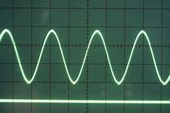
@zebulon1, do you have any ideas as to what I may have done wrong. I used 2 different pre-amps and once the volume gets near half way with speakers hooked up they sound really distorted and somewhat pop on left and right. I am a bit confused about the waveform pic in the spec 2 service manual. It says "
While the voltmeter indicated 30V/(40 ), adjust VR2 to just distorted point the upper half of the waveform. In the same manner, adjust VR3 to just distorted point the lower half with 28.3V/(44)."
When I adjust VR2 the upper half went distorted and when I adjust VR3 the upper half went distorted, not bottom half. My waveform looked similar to the one below before distorting. Am I using the correct waveform?
Attachments

Last edited:
xXColdShotXx
Active Member
Yeah, I get it to 30vAC with the sine wave and the input knobs around 3/4 of the way, then fine tune it with the pre-amp volume. When it hits 30vAC I adjust VR2 to where it starts to clip/distort. Then I adjust VR3 to where it starts to clip/distort at around 28vAC.