
Bill, again, I suggest you 'detach' the output section from the 'driver' section and isolate if the hum is in the output circuit itself, or if it's coming through the driver tubes. This gets a WHOLE lot easier if you can eliminate possibilities rather than shot-gunning 'fixes' by trying things when you don't yet know the cause. I 'get' the idea that this approach can eventually identify the cause.....but I still like the idea of finding the problem without 'modding' things. This is often the reason I go ahead and get an amp up and working first, then start 'modding' and adding things like IBAM. Of course, I often like the results of the 'original' product...and do away with all the additional mods. Just 'lazy' I guess........lol. Anyway...... I'm watching your progress and wishing you all the best. WC

You are using an out of date browser. It may not display this or other websites correctly.
You should upgrade or use an alternative browser.
You should upgrade or use an alternative browser.
Started a Rowe R-4359A amp conversion
- Thread starter Schmidlapper
- Start date
Schmidlapper
Super Member
Wharfcreek, Not sure what you mean by detach output section from the driver section. Do you mean pull the output tubes? If I pull the driver tubes the hum is virtually gone and the hum is not affected by the volume control and it is equal in both channels. Knowing those symptoms my train of thought was it must be something common to both channels. The first two things that come to mind that are common is the bias voltage and the heater circuit. On its own the bias voltage is smoothed half wave, it would manifest as 30 cycle noise, but if it were picking up the noise from the heater circuit it would feed the grids with 60hz noise equally in both channels. So I have been trying to minimize the heater AC noise impacts. This so far has netted me nothing, but I still haven't lifted the heater voltage properly, nor tried the noise pot route. I am interested in detaching the sections but can you elaborate? Is is like the separation of the bus I talked about reading? In that scenario the instructions were to capacitor cupel the two sections. In another version it was cupeled via a < 1 ohm resister, which I didn't try.
Hi Bill,
What I was referring to was to simply 'detach' the coupling cap that brings signal from the phase splitter of both channels from the output tube 'input' grids. By doing this you can more or less rule out the output section and the power supply filter section. If the amp is basically dead quiet without signal coming from the 'driver' tubes TO the power tubes, and I mean literally..... not just in the form of turning down any level controls ..... if the output section has no 'hum' being generated from within those tubes to the OTs....then you can pretty well rule out anything in that section of the amp...... or so I'm told. May not be 'completely' true......but I'm under the impression that it's true enough that it makes it not only worth the try....but worth looking more at the signal tube area if the amp IS quiet under these circumstances. I'm unsure if pulling the signal tubes accomplishes exactly the same thing....perhaps it does. But, with the caps still able to feed signal from that section...... if there is something being 'inducted' into the driver area...then who knows...... maybe with the coupling caps still connected maybe something 'could' find it's way to the power tubes and become 'amplified'. In any event, it's a quick and easy thing to try. As to that 'ground bus', I didn't have that in my amp....and seemed to work fine without it. I've worked with bus connections like that......my RCA RS177 amps had that kind of thing as did some of the other 'console' amps I've worked on. I don't see it being a problem....but again, anything's possible. At this point I'd look more for an 'error' some place. Either a voltage too high or too low.....a connection either 'made' that shouldn't be (like you mentioned about your filament wires), or 'not-made' that should be; in particular a 'ground' wire. Paul (Secret4mula) was just telling me about a Baldwin amp he just made and it was giving him fits...until he realized he'd not 'grounded' the ground side of the output transformer's output. He had the feedback hooked up properly, but the 'ground' side was just connected to the - speaker connection and had not been brought back to chassis ground. Once that 'fix' was rendered, the amp performed beautifully. So, sometimes something both simple and seemingly obvious can make a huge difference. Dave Gillespie caught me in a reversal of my feedback wires.....when I would have sworn I had them phased correctly. I just reversed my connections and it was like a miracle had occurred.
Tom D.
Schmidlapper
Super Member
I will give disconnecting the coupling caps a try, it will add more data, and is different than just pulling the tube. Yes, I read about your phase reversal issue. Paul's drawing appears to be an adaption of two halves of two different models, and mine is even a third model from that. One change in particular I never fully figured out is in the the power filter chain, the final drawing has three 1k resisters in it, mine came with two 1k and a 6k in the last position, with the same cap compliment. I followed the drawing since everything else was built to it, figuring electrically mine for all intensive purposes had become the hybrid model shown in the drawing. So your right if there were an error in that design, I made it. At the time I wasn't aware that it was just Pauls design. I have not been able to reach him and confirm if he had to make any further adjustments. I chose to include the IBAM MOD during build, because it makes sense to me to have it, and with the level of deconstruction I was making to rebuild the unit, it was easier to incorporate it then. The final bias voltage divider set that I got to work, by the way was a 5K and 3.3K. Now when I change out the output tubes I will see if that remains the case.
Schmidlapper
Super Member
I used some NOS drive tube sockets I had on this with a metal upper ring half and a lower socket assembly with some ground loops on it, should I have grounded this to the bus? The chassis paint may be isolating them, do they add any shielding of the tube pins on their own I may be lacking? They are visible in several of the previous photos.
OK, taking your comment about the chassis paint possibly 'shielding' the tube sockets, that IS a possibility. The tube socket itself isn't really part of the program 'electrically' unless it incorporates an upper shield.....which when attached to the socket can be a 'grounded' RF shield. In the case of the Rowe amp, it never had this in the first place, so I don't see where it would either be necessary now, nor part of your problem. That said, if you're attaching other 'ground' wires to the connection tabs on the socket, and the socket isn't properly grounded, the YES... you could have a big problem!! And, yes, you could resolve that by simply connecting your sockets to the ground buss you've already established.
As to the PS resistors connecting the PS filter stages.....IMHO these are really more of a 'starting point'....particularly in today's world. I look at this as being something to 'work with' in getting the voltages at the different stages at the level I want them. Of course, there will be limits. But, the amp was probably designed and built when outlet voltages may have been a bit less......so the idea of having to increase some resistance in the PS stage couplers to get voltage down isn't surprising. However, as I believe most people would agree....the more 'resistance' you add to the PS, the more the performance of the amp 'may' suffer. I some cases so minimally it can only be detected with test equipment if even then. However in some other cases you may actually here the amp 'farting out' (as I like to call it).....when the PS voltage simply can't keep up with the musical demand. So.... a lot to consider. This is why I start with just getting an amp working in 'stock' configuration.....so I know I have a functional starting point....then I can gauge my 'mods' as being either improvements or detriments accordingly. But, again, I understand your approach. Unfortunately, you weren't aware that Paul's design was somewhat 'untested' at the time he posted it. However, he DID eventually complete a functional conversion using all his updates and with a functional IBAM...... but like you, he did have to 'tweak' the values some.
Going back to the hum issue....... if you 'detach' the output stage from the driver stage by disconnection all 4 coupling caps (leaving bias voltage supply in tact), and then 'test' the output stage alone, I think this will be pretty 'telling'. Your comment that the hum is in both channels equally is also rather significant, as you indicated, by reflecting that which is in common to both. So, if NO HUM on output section 'uncoupled'....then I'd go for voltage issues on the driver supply side, and perhaps even question the quality of my PS filters. Not impossible you've got a bad electrolytic.
Tom
Schmidlapper
Super Member
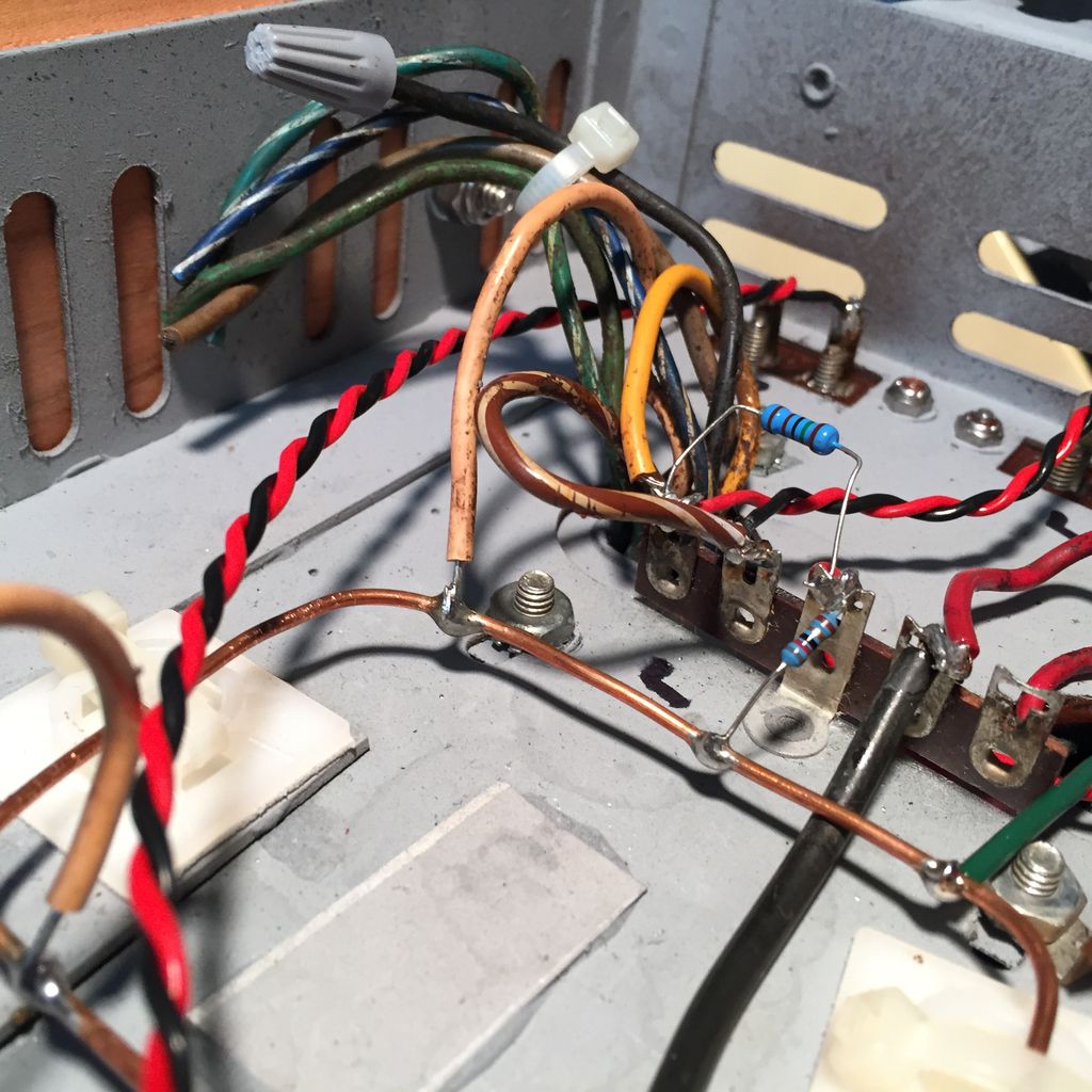
Who likes a mini mystery? Your looking at the Left OPT, feed back circuit and speaker interface, Right is the same. See anything odd? 

Schmidlapper
Super Member
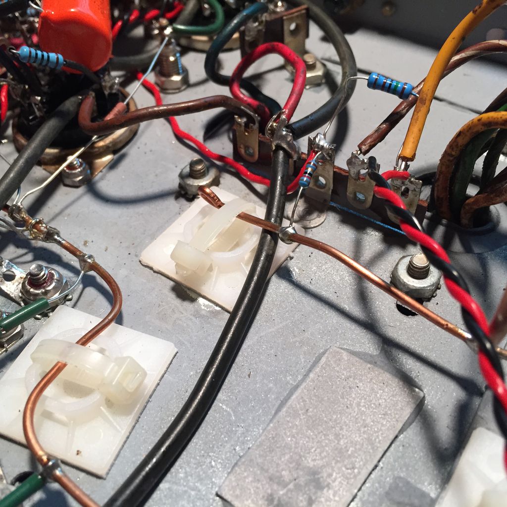
Here is the right channel side, it may be easier to see on this side.
Bill,
Your yellow wire.....formerly E1, should be your feedback wire. I can't tell exactly from the pictures, but it looks to me like you're taking some kind of resistor from that yellow wire, going to yet another resistor, and then going directly to ground. If this is true, this I believe to be in error. First, the former A1 and A2 wires for the 70V outputs should simply be nipped off and NOT connected to anything. Next, your former E1 wire....which I believe you are now designating as one of your two speaker taps....the Yellow wire....that should not only go to one of your two speaker terminals, but a 1.5K (1500 ohms) resistor should go back to the dividing network on pin 3 of the driver tube.....with one end going to another 1.5K resistor and directly to pin 3....and the other end going to an 82ohm resistor to ground.
The green wire (Former E2) should be tied off, your former E3 (Brown-white) can be your other speaker connection wire, E4 needs to be transformer Ground as per Tom Bavis's prior entry, and E5 (blue white) and E6 (Green white) also need to be tied off.
What is the value of the resistor you have coming off the yellow wire now, and why is there a second one in series with it to ground? I'm thinking this may be part of your problem. Maybe go back and look at that part of the schematic and double check your work.
Feel free to call me to discuss if you wish: 410-925-7213
Tom D.
Schmidlapper
Super Member
Everything is wired per the drawing, the issue is I mistakenly used the grounded tabs and not the ungrounded tabs like I had planned to do when laying it out. The feedback circuit was going straight to the chassis ground. I finally caught it while looking over everything this afternoon, I knew immediately when I finally noticed it. Just as you say, E1 goes to speaker +, and provides feedback through the 1.5k resister, which then has an 82 ohm resister off of it to ground, and a connection to pin three of the drive tubes (the red wire). E3 then goes to the speaker minus connection, and finally E4 goes direct to ground, all just as the drawing shows, the rest of the OPT wires are not connected. The hum is now essentially gone, hallelujah. I ordered up a quad of output tubes for it to celebrate. That bad output tube is way to harmonic, and it won't stabilize its bias, so I really can't trust using it. I will keep the other three as spares. For the time I did listen to it even with the bad tube, it sounded great.
That 'feedback circuit' will get ya every time!!.....lol Good Job Bill! Tom
Glad you got it worked out. I looked right at the grounded terminal point in your pictures and didn't click. Give us a bit of a review once you've been able to use it for a bit. I see these on the auction and they aren't too badly priced if the iron is good.
Best,
John
Best,
John
John, I'd give the iron in these old Rowe amps a real 'thumbs up' as far as performance goes. I'm quite a 'Scott' fan, with a number of Scott 7591 amps. I've got an old LK-72 that I kind of consider as my 'benchmark' of performance when dealing with either 7591 or 7868 amplifiers. While I'd not say that the Rowe is 100% equivalent, I think the real performance detriment is perhaps at the upper end of power output level. The Scott may simply have a bit more 'guts', or 'headroom' as some might put it. However, that said, these Rowe amps can give the Scott a real run for the money, particularly in the mid-range of power output, and certainly in the overall fidelity. I'll make note of Bob Carver's comment about having tested the OTs and found them to be nearly flat all the way from about 16hz up to about 60Khz. I take that with a grain of salt.....but still......if it's truly good from 20 to 20K, or even 18K, then I'd put that well within the 'Hi-Fi' category. Give one a try.....and please let me know if you do. I'd love to get a group together around these old amps.
Bill, I now follow you....... At first I wasn't sure what you meant by 'grounded lug', but then I realized you were talking about one of the lugs on the terminal strip. So, clearly your feedback was NOT going where it should be.....lol. I take it the first resistor is the 1500 ohm feedback resistor, the second that is connected to your ground buss is the 82 ohm resistor, and the red wire seen coming off the 'grounded lug' is the feed to the other 1500 ohm resistor which feeds the first cathode (pin 3) of the driver tube...... Like John, I didn't catch the grounded lug either....but now I see it plain as day........... and I can admit to having made similar errors in the past. I now try to remember about it......but if not working with this stuff regularly (and I mean almost on a daily basis), it's easy to overlook something like that. But, good catch, and glad it's working well.
Paul has got me now deep into a Baldwin project amp. I'm not sure just what the chassis number is that served as 'donor' for this project, but I got one from an old organ that had a PPP stage for the main amp, and a PP stage for the 'Leslie' driver. All using EL84 output tubes. Paul had the same amp, and had been looking for a mate for his PPP output transformer, so I simply swapped him mine for his PP OT. He's now going to build a FrankenAmp of some kind...while I'm going to attempt yet another build using just the PP OTs. So.....the projects 'rock on'..... I may seek your advice on this next build of mine.
One last comment here: I've used this Rowe driver circuit now in a few other amps. I've copied it into an old RS177 RCA, an old Madison Fielding Console amp that had actually caught fire....and I even fabricated it into an old Rock-Ola amp. I've had stellar luck with it, as all the amps sounded wonderful...and I was able to get things working with minimal effort. My point is that it seems to be a very versatile design, easy to work with, and very 'functional' from a general standpoint. Sadly, I never really got to do a lot of 'testing' on all those amps...other than many hours of fine listening...but reports from their new owners all came in with high praises. So, you may want to keep a copy of that part of the schematic just for another project down the road.
Best, Tom D.
Schmidlapper
Super Member
Wanted to let everyone know latest state of this project. I have continued plugging away at lowering the noise floor, and through trial and error I have rebuilt the ground system pretty much following the valve wizard's suggested order, lifted the AC heater circuit on 30 VDC and added humdinger, spent this morning tapping and jiggling every component while listening until I found any odd noises from speakers and uncovered three subpar solder joints, now all fixed. Then moved the output tube screens off of the B+ To the OPT on to a better filtered stage. I have been able to get the right channel AC down to .001V and the right to .005V of 60hz and no 120hZ. When I moved everything back to the main setup the hum was very loud again, it measured iat 35dB and I was feeling discouraged. So started diagnosing what went wrong from workbench to livingroom, the left channel was now measuring over .225 VAC, I pull that driver tube and it turned out to be a bunch of flux in the socket. Having 103dB sensitivity is as much a curse as a blessing, as .003 VAC average between channels is audible up close, but not so much at my listening position. Now all this effort has made the background really disappear and the music stands out very crisp, and clear. Have replaced all the original tubes with Sylvania 7868s outputs, drive tubes are NOS JAN Phillips 5751s, and the rectifier is a NOS JAN Phillips 5U4GB. Hobbies, geesh!
Schmidlapper
Super Member
Question, the humdinger I am using is 500 ohms with 30vdc on center tap all pretty straight forward. To get the lowest AC ripple .001 & .005 VAC, I have to adjust it all the way to one side, is that indicative of something? If I had used a 750 ohm pot might I be able to adjust this down even more? Would adding a 100R in series with the other side of pot shift me and give me the same extra adjustment of a bigger pot?
Is a humdinger just a pot across the filament winding? If so, then all the way to one side is all the way. You've got one side of the filament winding effectively grounded for AC assuming your 30V elevation has a cap to power common. More resistance won't make a difference. Where/how do you pick up the 30VDC offset?
Schmidlapper
Super Member
Is a humdinger just a pot across the filament winding? If so, then all the way to one side is all the way. You've got one side of the filament winding effectively grounded for AC assuming your 30V elevation has a cap to power common. More resistance won't make a difference. Where/how do you pick up the 30VDC offset?
Voltage divider off the second filter cap. So I could just remove it, and put the DC to the one heater leg and get the same result then? Is it normal for the pot to have no effect when referenced to DC rather than ground?
Jaymanaa, it's from the mid to late 80s timeframe. I've been hard on it through the years, but it was built to last.
Last edited:
Schmidlapper
Super Member
So after thinking about the last post awhile I went back and grounded the humdinger center tap, removed the DC lift circuit all together, direct grounded the OPT's to the resivour cap, rerouted the right channel drive circuit ground wire. Adjusted the humdinger with inputs grounded for the lowest AC on the speaker outputs. The final verdict, I am down to an equal .002 VAC on both channels and it is barely audible on the Klipsch. So without further ado the amp stats; B+ =358v, B+1 @ 2nd filter =324v, B+2 @ 3rd filter =321v, Bias circuit -18.6, heater circuit 6.5vac, cathode bias @ 40mA. Wife asked me what finally fixed it, I told her, "it got tired of me."
Schmidlapper
Super Member
Similar threads
- Replies
- 169
- Views
- 13K
- Replies
- 59
- Views
- 3K