
I find it easiest to remove the heatsinks and transistors as a single unit.Any hints on how to properly dismount and remount the output transistors with new thermal compound?

You are using an out of date browser. It may not display this or other websites correctly.
You should upgrade or use an alternative browser.
You should upgrade or use an alternative browser.
Suggestions/advice for M-80 service....
- Thread starter analog addict
- Start date
analog addict
Glory or Death!
I find it easiest to remove the heatsinks and transistors as a single unit.
https://flic.kr/p/V9FShY
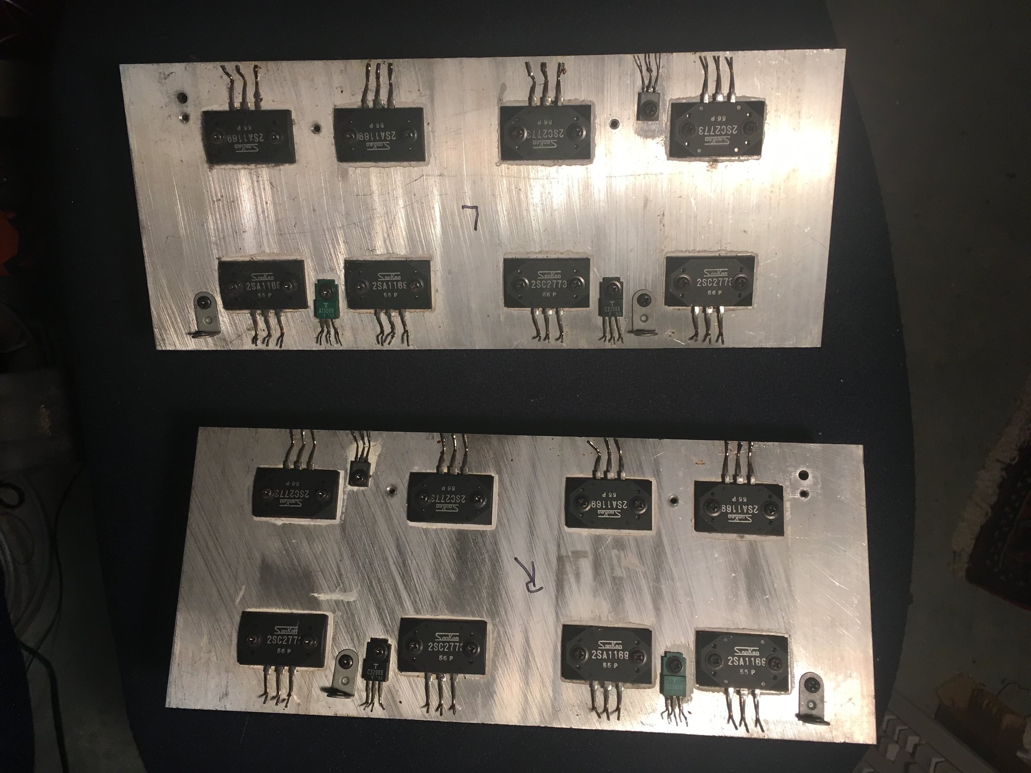 Untitled by Analog Addict, on Flickr
Like this? I've had these apart like so. I assume I remove the output packs one at a time, clean them, and then reapply the thermal compound. However, I've not used the thermal compound before. How to best apply it?
Last edited:
analog addict
Glory or Death!
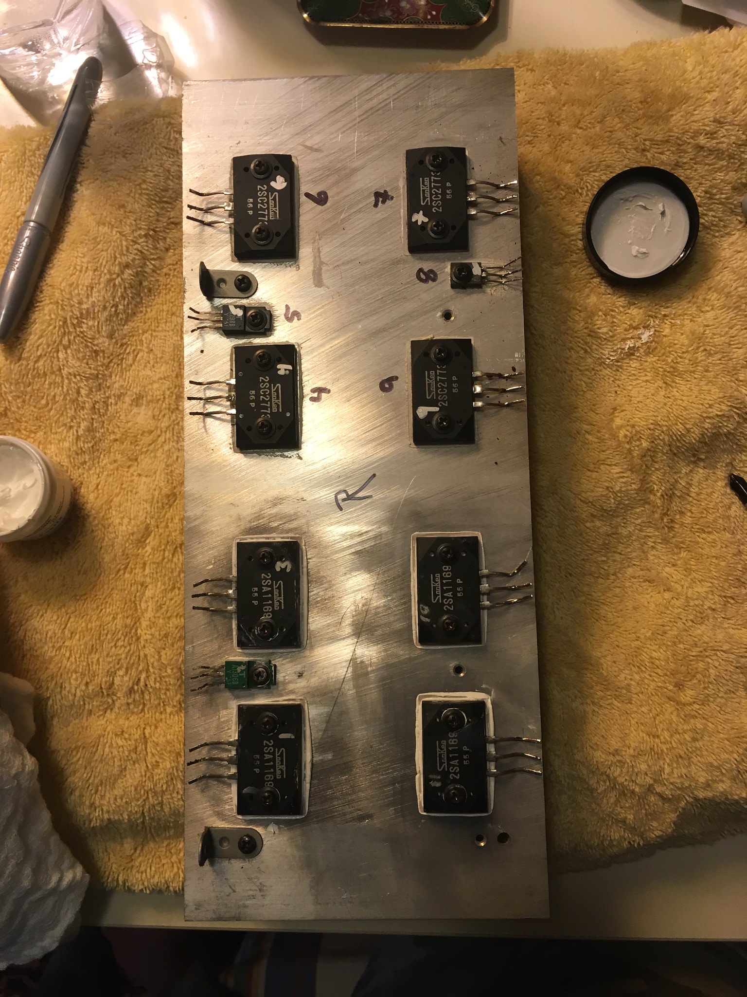 Yamaha M80 by Analog Addict, on Flickr
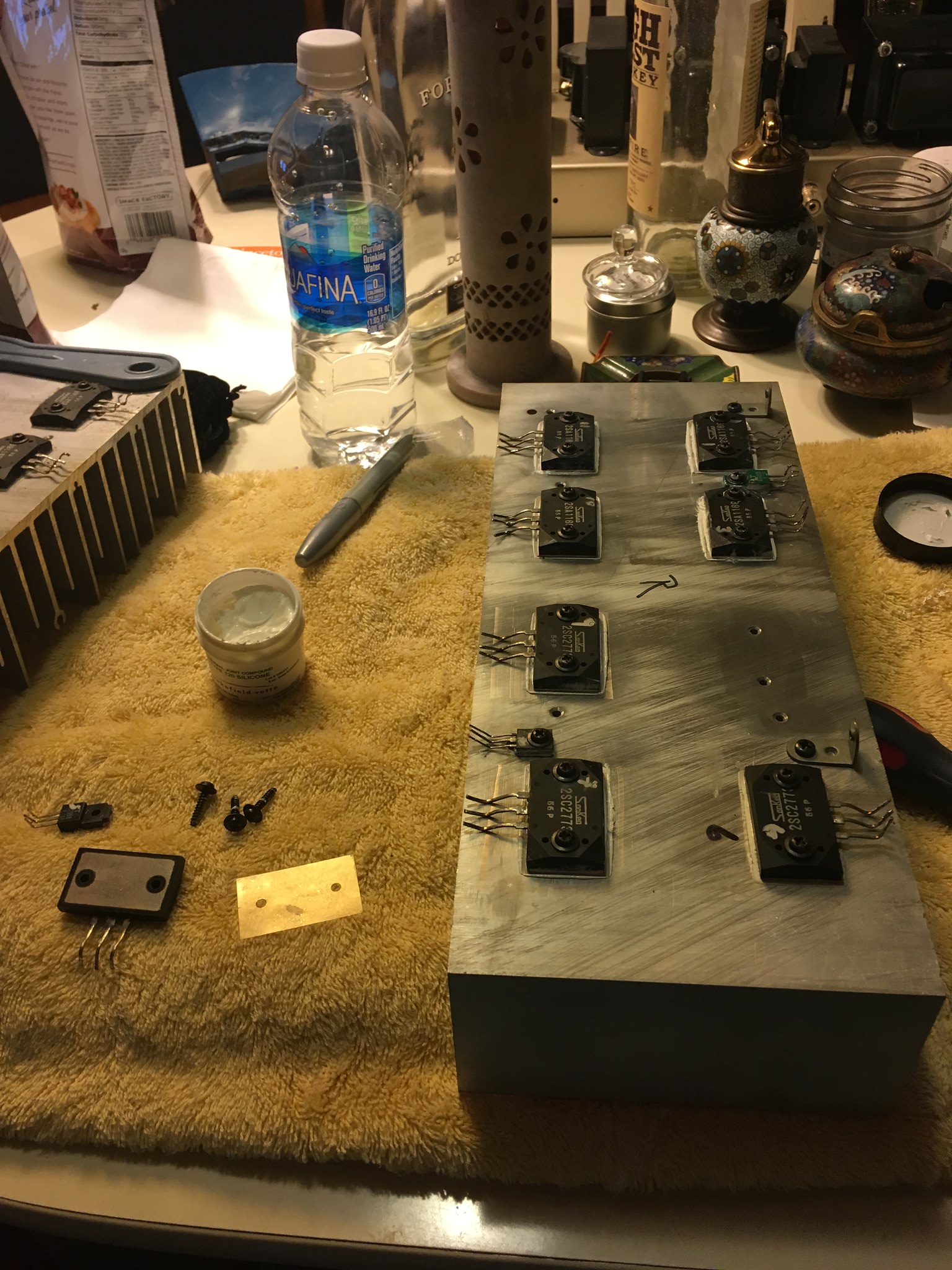 Yamaha M80 by Analog Addict, on Flickr
Half redone. Trying to do a thin even coat of this stuff. it's definitely messy as hell.
Looking at these contact pads, I was initially confused by the additional components in the vicinity, but realized that everything on the same pad/box of the PCB was electrically connected anyway, and so I could safely solder it all together....
 Yamaha M80 by Analog Addict, on Flickr
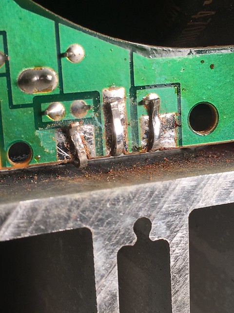 Yamaha M80 by Analog Addict, on Flickr
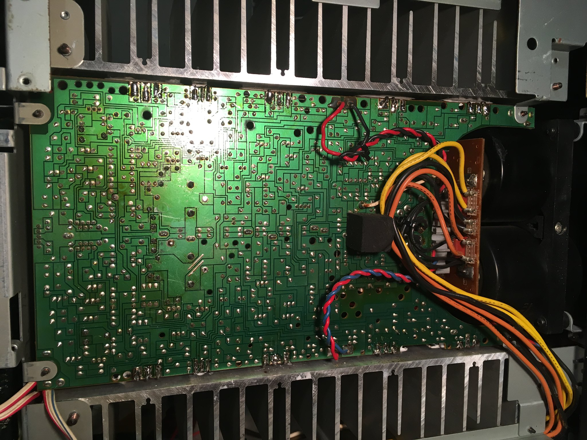 Yamaha M80 by Analog Addict, on Flickr
Bottom side finished. Need to solder the topside to the PS boards, and then figger out the protocol for biasing
Last edited:
analog addict
Glory or Death!
Ouch. You're killing me. if it needs it, it needs it.
Tell me what you're looking at, since I haven't learned how to recognize this issue
Tell me what you're looking at, since I haven't learned how to recognize this issue
It depends how much you care, if it's something you plan to use daily/regularly as a major part of your system it's probably worth doing.
If you're just selling on or repairing for someone else then maybe it's fine to just do the obviously bad ones. Personally I find it's just faster to redo a whole bunch (I usually just add some fresh solder to the existing joint) than to try and decide which questionable ones are actually bad.
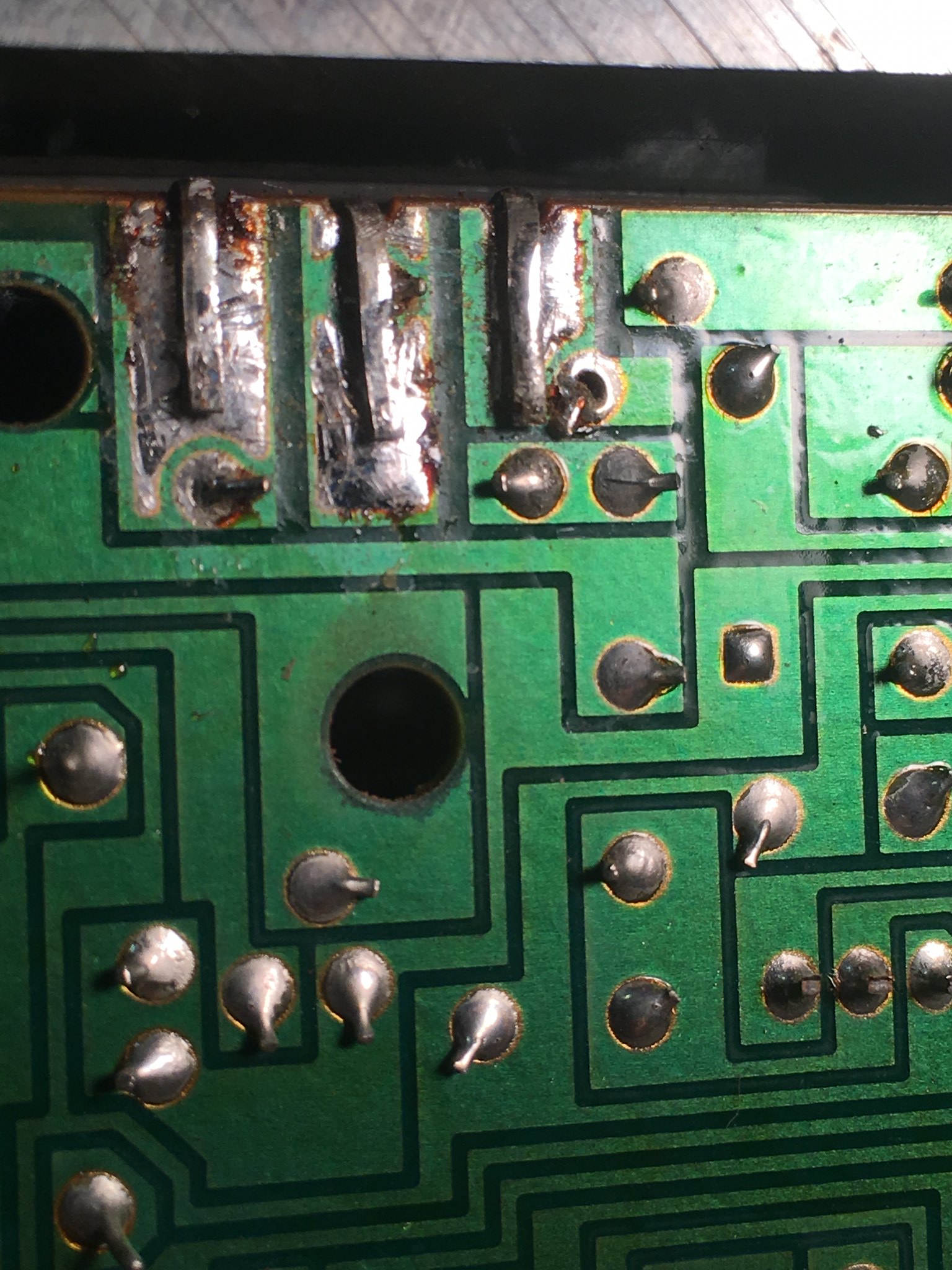
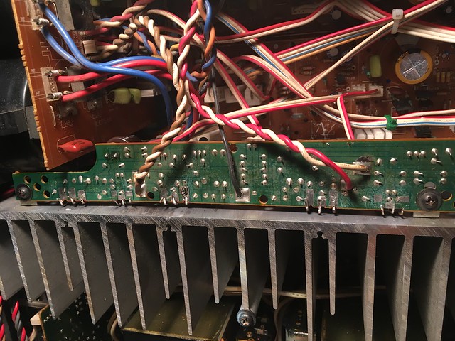
I circled some examples, the secondary ring in those joints is a crack. These will usually conduct (but less well than a good joint), and after more heat cycles or movement can develop intermittent connection causing other issues.

A good joint has a nice bulb of solder and dries shiny (not matte), so in my opinion most joints on vintage gear (not just Yamaha) are average at best.
If you're just selling on or repairing for someone else then maybe it's fine to just do the obviously bad ones. Personally I find it's just faster to redo a whole bunch (I usually just add some fresh solder to the existing joint) than to try and decide which questionable ones are actually bad.
I circled some examples, the secondary ring in those joints is a crack. These will usually conduct (but less well than a good joint), and after more heat cycles or movement can develop intermittent connection causing other issues.
A good joint has a nice bulb of solder and dries shiny (not matte), so in my opinion most joints on vintage gear (not just Yamaha) are average at best.
analog addict
Glory or Death!
Thanks. Always learn sumphin new at a place like AK....
analog addict
Glory or Death!
 Untitled by Analog Addict, on Flickr
Went through and redid every joint on this board. Hope it's worth it.....
Went through and redid every joint on this board. Hope it's worth it.....
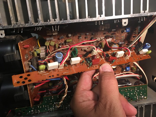
Don't forget the two APS boards on top.")
Quick question for @analog addict or @avionic, what's the diameter of the original 1000uF / 100V Muse caps in there?
analog addict
Glory or Death!
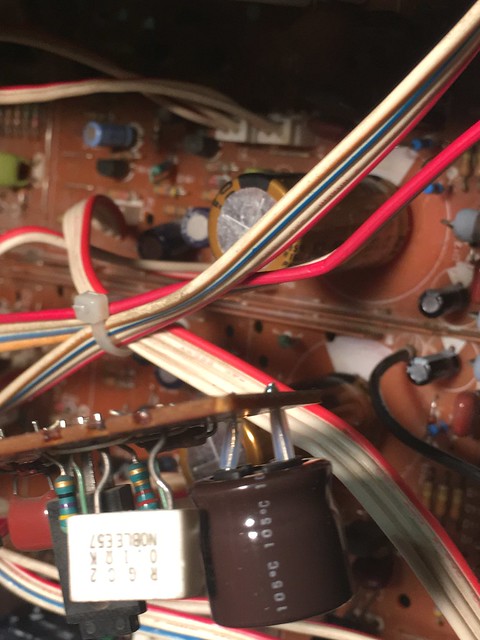
Before...
 Untitled by Analog Addict, on Flickr
After
 Untitled by Analog Addict, on Flickr
I used Nichicon 100uF 100V caps instead of 100uF 50V Rubycons. The old caps actually tested fine, but I replaced them anyway.
 Untitled by Analog Addict, on Flickr
Also touched up all the solder joints on these boards.
Before
 Untitled by Analog Addict, on Flickr
After
 Untitled by Analog Addict, on Flickr
I'm ready to fire this thing up, but wanted to know is there any particular procedure for power up, etc? I need to check the bias since I replaced the bias pots. Any tips? Just follow the procedure in the other thread?
Untitled by Analog Addict, on FlickrAfter
Untitled by Analog Addict, on FlickrI used Nichicon 100uF 100V caps instead of 100uF 50V Rubycons. The old caps actually tested fine, but I replaced them anyway.
Untitled by Analog Addict, on FlickrAlso touched up all the solder joints on these boards.
Before
Untitled by Analog Addict, on FlickrAfter
Untitled by Analog Addict, on FlickrI'm ready to fire this thing up, but wanted to know is there any particular procedure for power up, etc? I need to check the bias since I replaced the bias pots. Any tips? Just follow the procedure in the other thread?
I'm ready to fire this thing up, but wanted to know is there any particular procedure for power up, etc? I need to check the bias since I replaced the bias pots. Any tips?
- Adjust the bias to minimum (if you didn't match the value to the original pot setting, preferable).
- Fire it up on a dim bulb tester, you can use a 100W bulb
- Make sure the relay clicks a few seconds after turning amp on (with speaker switches on)
- Make sure the bulb glows brighter when you hit the Class A switch and dims again when you turn it off
analog addict
Glory or Death!
Heh, guess I better finish building a dim bulb tester. Should I use this service manual, or a M-85 SM?
http://sportsbil.com/yamaha/m-80-sm.pdf
http://sportsbil.com/yamaha/m-80-sm.pdf
Last edited:
analog addict
Glory or Death!
Well I guess it's back to square one. DBT goes bright on pressing the power button. Shut it off immediately. The question becomes now what?
clinic-audio
all on YAMAHA untill 1990
Sorry , I hope this is not too late ...
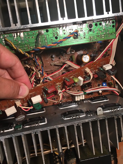
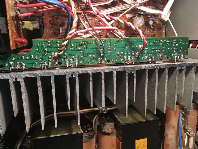
Be very carefull with your power transistors connections , some are are really closer to make a short with heatsink surface !!

the last one on the right in the midle of the 3 legs is the collector and this is here we have the power supply voltage , a short here will be drastic for the power supply of your amplifier !
Double check on the both heatsinks before to switch the power on !!
Be very carefull with your power transistors connections , some are are really closer to make a short with heatsink surface !!
the last one on the right in the midle of the 3 legs is the collector and this is here we have the power supply voltage , a short here will be drastic for the power supply of your amplifier !
Double check on the both heatsinks before to switch the power on !!
Well I guess it's back to square one. DBT goes bright on pressing the power button. Shut it off immediately. The question becomes now what?
Good thing you built the DBT!
First thing I'd check is that your new bias pots are actually set to the end that gives min (not max) bias.
Then look over for shorts, especially between power supply wires and between transistor legs. Make sure no pads have lifted from the board, and check no legs are touching the heatsink like clinic said.
Some of the jumpers around the output transistor legs come very close to touching the legs too, so double check for solder bridges there.
Set fully CCW.First thing I'd check is that your new bias pots are actually set to the end that gives min (not max) bias.