

You are using an out of date browser. It may not display this or other websites correctly.
You should upgrade or use an alternative browser.
You should upgrade or use an alternative browser.
SX-1980 power supply problems
- Thread starter txturbo
- Start date
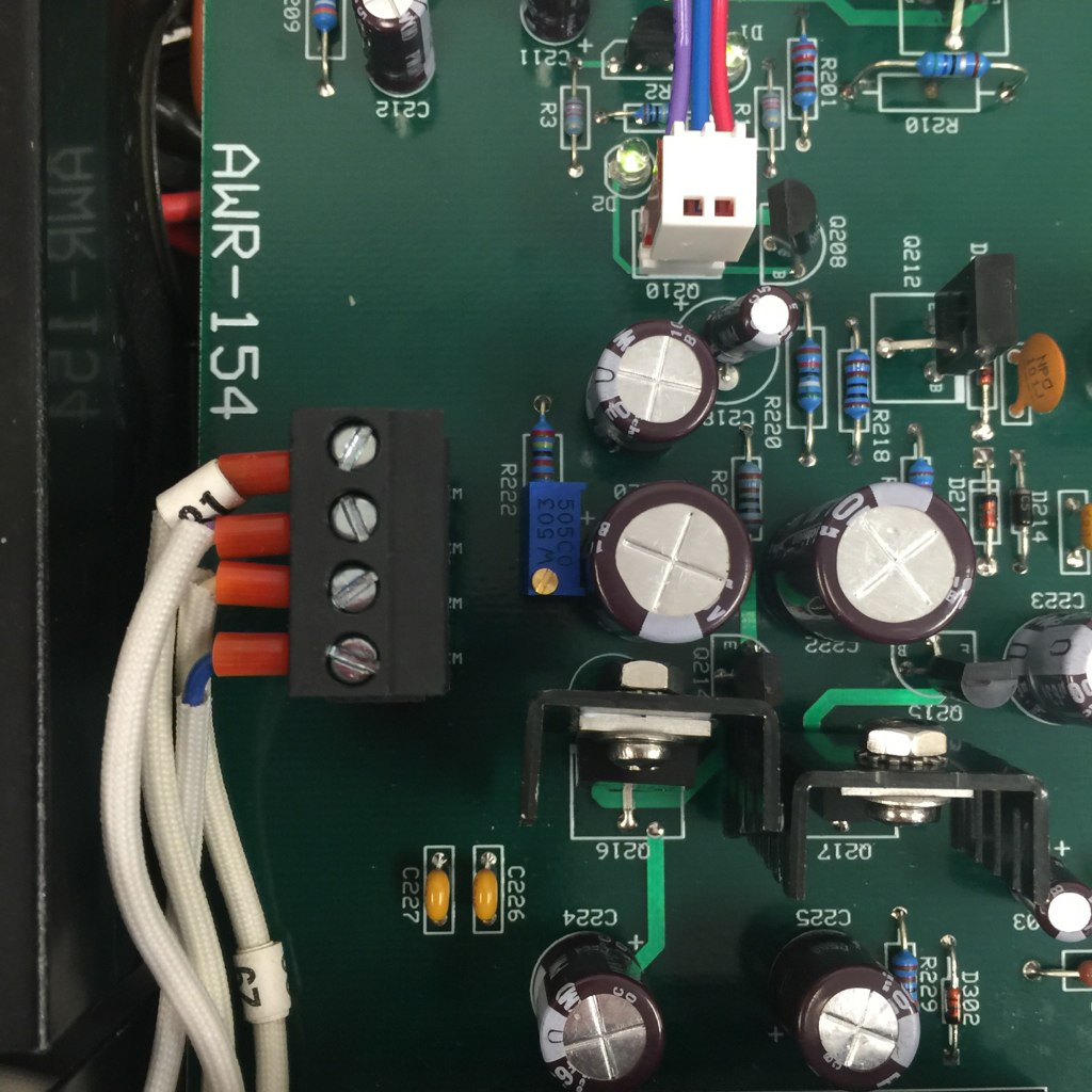
Ended up using scotch brite :yes: I tried an eraser but I did not have a good one that I could get at the back of the pins. I also tried tarnex, did not touch the oxidation. I also recaped them and installed the new trim pots. Now it works again so good call on the pin cleaning. :thmbsp:
I think what I'll do next is just finish recapping the unit and clean all of the controls and install the trim pots for the 80v.
One other issue is the FM tuner. Tuning at the low end of the dial is not good.
Once it's stable I am going to let it run non stop with all of the covers on for a week.
I think what I'll do next is just finish recapping the unit and clean all of the controls and install the trim pots for the 80v.
One other issue is the FM tuner. Tuning at the low end of the dial is not good.
Once it's stable I am going to let it run non stop with all of the covers on for a week.
The pencil eraser trick is to take a #2 pencil with eraser on the end, make a small channel down the axis of the eraser with a needle, and to slip the pin into this channel. Then TWIRL the pencil.
The lowest 4mm of the pin isn't reached by the connector contacts, thus don't need to be as clean.
The lowest 4mm of the pin isn't reached by the connector contacts, thus don't need to be as clean.
Thinking too much,Anyway... I got to thinking...
") I agree with EW leave them as is.
I agree with EW leave them as is.Thinking too much,
Yea.. I tend to do that a bit too much... That's how I get into this kind of crap to begin with.

I have been running the receiver at decent power levels for a couple days now and every thing appears to be OK. We ordered some parts form Mouser to test out the 80V adjustment, should be in tomorrow. At the moment it's quite stable at +/- 77V.
I took a few temperature measurements:
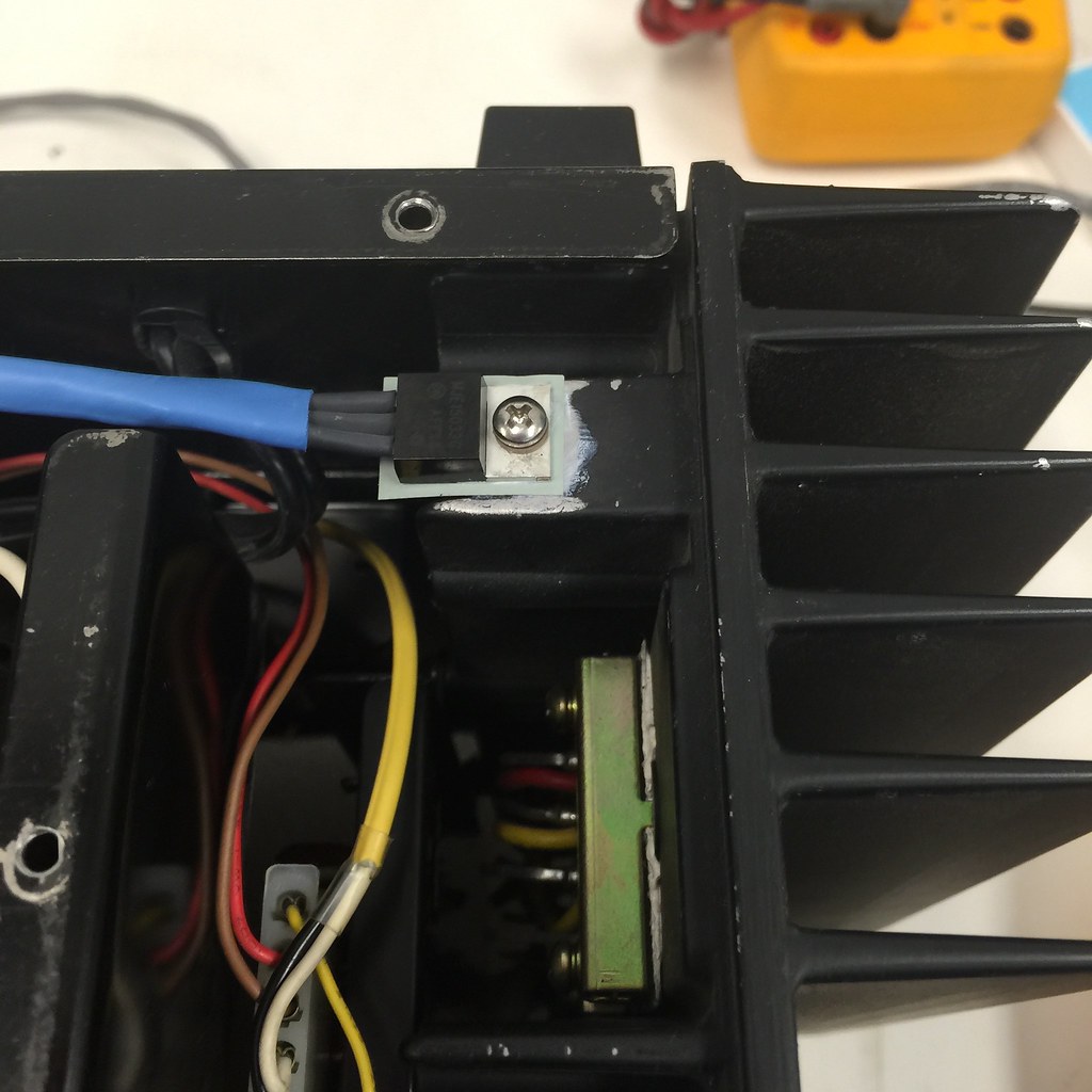
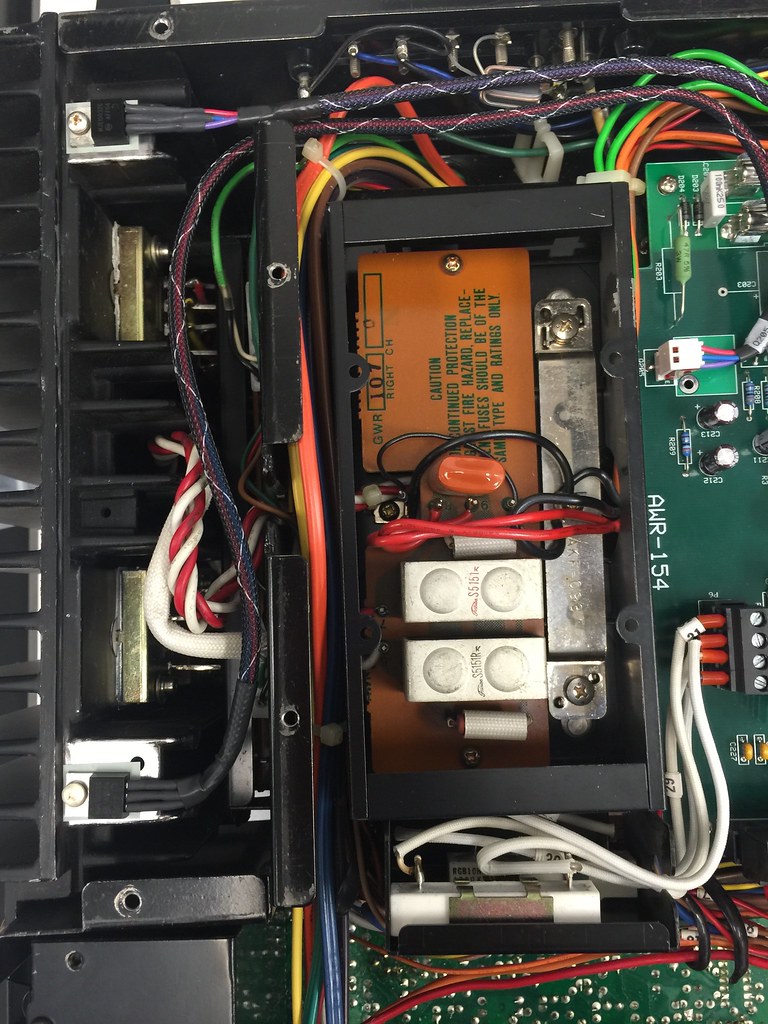
80V regs are running about 55 deg c as measured at the mounting tab. The heatsink is at 40 deg c. That's a 15 deg delta across the gap, not really all that good. I am using a Kapton isolator that's dry for this test. We have a few other materials to try with and without paste. I would like to get the gap much lower without having to modify the heat sink by drilling and sanding it. This way the existing hole can be used to mount the transistor.
Q203 and Q205 are running about 60 deg c at the tab. The heat sink is nearly the same so they are what they are.
I will try and rig up some TC's and see what the temps do with the covers on and the receiver sitting upright.
FWIW, I've been removing the paint on the big heatsink before drilling the hole for the mounting screw (paint thinner and sandpaper). I've also been removing the paint from the inside of the existing hole and putting elect. tape under the bottom of the hole and filling the hole with JB Weld. Once set, I file it down and then sand smooth. This allows me to mount the transistor so the leads overhang the heatsink and the connector can slide right on to the leads without having to bend the leads around so the connector can clear the heatsink.
The existing hole is enormous, and AFAICT, essentially useless as a mounting point. Better if it wasn't there at all...so I get rid of it.
On the units that I've done, I've seen a pretty small temp differential between the big heatsink and the transistor tab. Probably under 6 or 7°C.
The existing hole is enormous, and AFAICT, essentially useless as a mounting point. Better if it wasn't there at all...so I get rid of it.
On the units that I've done, I've seen a pretty small temp differential between the big heatsink and the transistor tab. Probably under 6 or 7°C.
I did a bit more testing of temps.
First, I put a bit of grease between the Kapton isolator, heat sink and transistor on the left channel for the 80V transistor, leaving the right one dry.
Left transistor tab = 52 deg c
Right transistor tab = 71 deg c
L+R Amp heat sink temp = 37 deg c
So the delta dry is even worse than I thought.
I think we will have some silicone pads to try today. Eventually I will drill the heat sink and attach the transistor. It's just fun to experiment.
Q203 and Q205 transistors are running at 58 deg c
Q216 is 45 deg c and Q217 is 38 deg
All of the temps are taken with the receiver upside down. With it upright and the covers on the temps will go up on the power supply board.
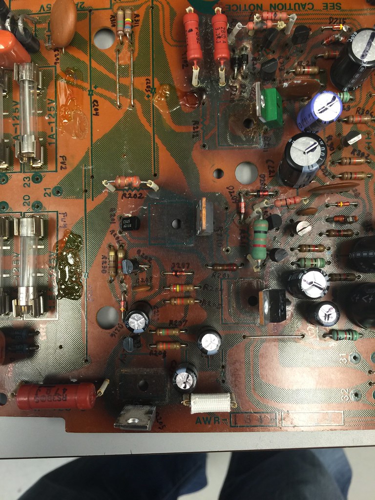
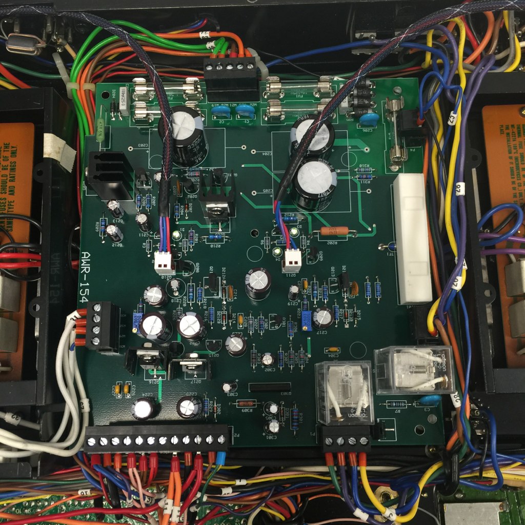
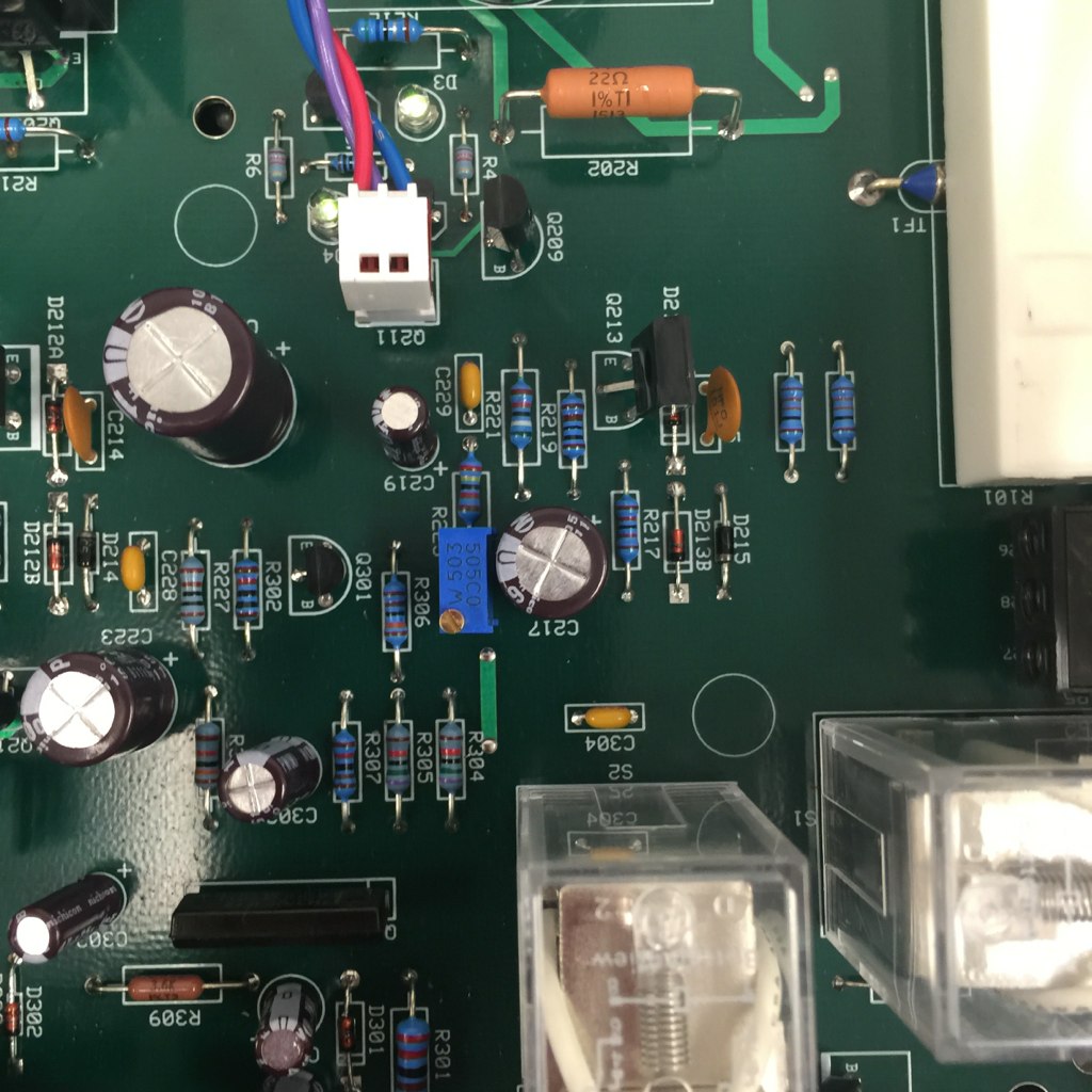
Looking at the old board it's easy to see that it suffered death by overheating. Not just the components but the actual board. If the heat were distributed evenly it would not be so bad but having concentrated hot spots provides such a thermal gradient that it caused the board to warp. Looking at the board it appears darker near Q203 and Q205 than the 80v's. I am sure that the new board is stiffer than the old one but not sure if it's going to fair much better in the long run without also moving Q203 and Q205 unless the new heat sinks can get the heat away from the board. With the board inverted I don't see how any improvement in the heat sink has much of a benefit if the heat has no where to go.

First, I put a bit of grease between the Kapton isolator, heat sink and transistor on the left channel for the 80V transistor, leaving the right one dry.
Left transistor tab = 52 deg c
Right transistor tab = 71 deg c
L+R Amp heat sink temp = 37 deg c
So the delta dry is even worse than I thought.
I think we will have some silicone pads to try today. Eventually I will drill the heat sink and attach the transistor. It's just fun to experiment.
Q203 and Q205 transistors are running at 58 deg c
Q216 is 45 deg c and Q217 is 38 deg
All of the temps are taken with the receiver upside down. With it upright and the covers on the temps will go up on the power supply board.
Looking at the old board it's easy to see that it suffered death by overheating. Not just the components but the actual board. If the heat were distributed evenly it would not be so bad but having concentrated hot spots provides such a thermal gradient that it caused the board to warp. Looking at the board it appears darker near Q203 and Q205 than the 80v's. I am sure that the new board is stiffer than the old one but not sure if it's going to fair much better in the long run without also moving Q203 and Q205 unless the new heat sinks can get the heat away from the board. With the board inverted I don't see how any improvement in the heat sink has much of a benefit if the heat has no where to go.
Time for an update:
We got the 50K trim pots and 24K resistors installed. After a a good warm up we can adjust them dead on at +/- 80V. They sit perfect even after several hours.
One thing I did notice is that the voltage increases with a rise in temperature, I did not check the span. I will check it again cold in the morning. I bet it's a volt lower.
Anyway here's to you EW, good call on the parts! :thmbsp:
I think I'll try and install the silicone pads and check the temps.
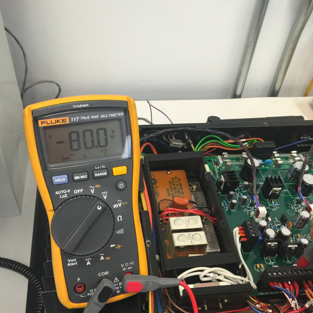
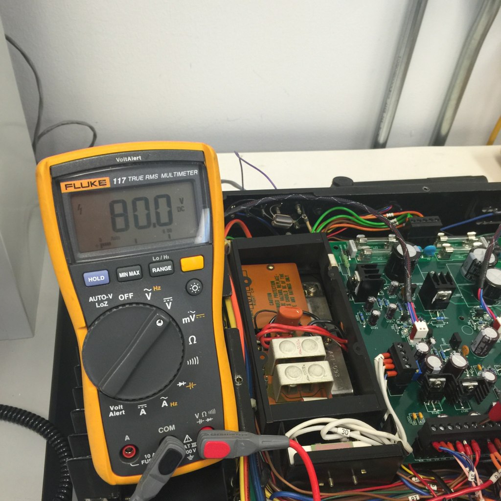
buildingnut
Active Member
Keeps getting better and better! Nice work! :thmbsp:
I tested the silicone pad with the paint removed and a bit of thermal compound.
Compared to the other side that has the paint still on and a Kapton isolator the temp is nearly identical. There is still a 10+ deg delta across the thermal gap between the tab of the transistor and the heat sink.
The next thing to do would be to drill the heat sink and get the entire transistor's tab and package onto the heat sink, as Glen had mentioned this should drop the delta to single digits.
jeffpaletz
AK Subscriber
Love the pictures, what a beautiful work of art.
Most silicone pads are junk. For a TO-220, I use these: http://www.digikey.com/product-search/en?keywords=BER113-ND
This is the last of the temp tests...
So I moved the transistors to the point of where they are completely in contact with the heat sink. I did not fill in the hole because in this installation the transistor is not covering the hole.
Final results:
~ Delta temp between transistor tab and heat sink
Transistor mounted with silicone pad, heat sink drilled, transistor positioned completely over aluminum. Delta T = 5 deg.
Transistor mounted with silicone pad using screw on existing hole. Delta T = 15 deg C
Transistor mounted with Kapton pad and thermal grease using screw on existing hole with paint removed from AL. Delta T = 15 deg C
Transistor mounted with Kapton pad and thermal grease using screw on existing hole with paint on AL. Delta T = 15 deg C
Transistor mounted with Kapton pad only using screw on existing hole with paint on AL. Delta T = 34 deg C
Typical heat sink temp after warm up is 37-40 deg c.
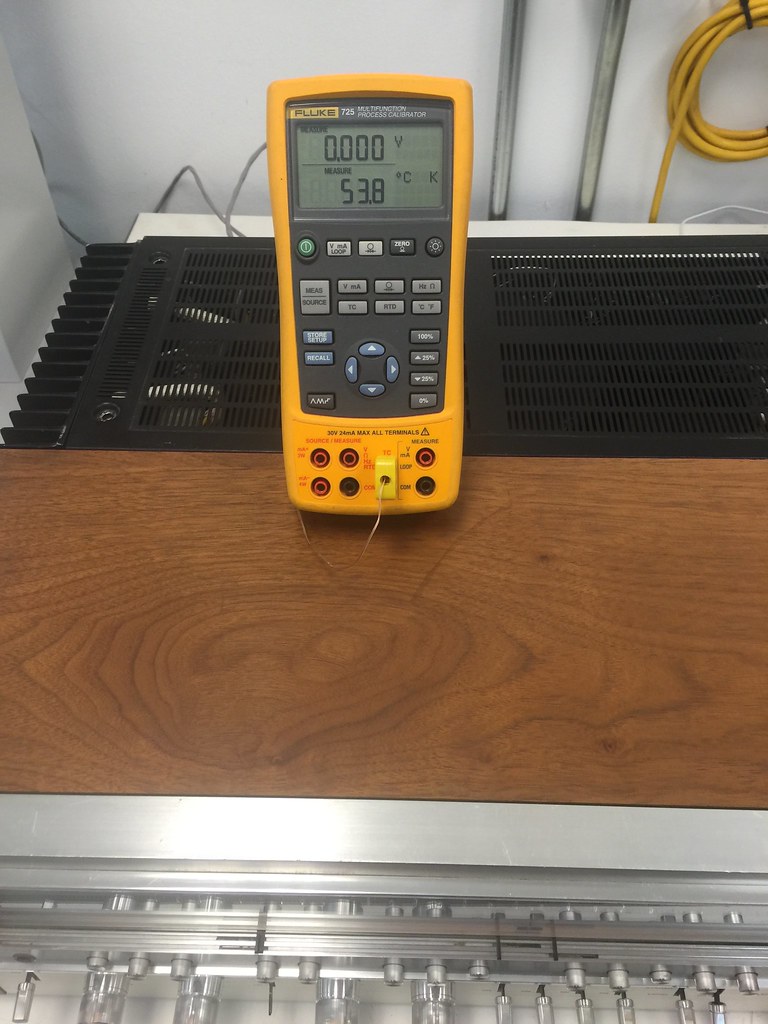
So then I placed a thermocouple on the Q203 (I THINK, COULD BE Q205) put the covers on and flipped it over.
It runs around 53 deg c with the music gently playing. I did not check the board temp.
So I moved the transistors to the point of where they are completely in contact with the heat sink. I did not fill in the hole because in this installation the transistor is not covering the hole.
Final results:
~ Delta temp between transistor tab and heat sink
Transistor mounted with silicone pad, heat sink drilled, transistor positioned completely over aluminum. Delta T = 5 deg.
Transistor mounted with silicone pad using screw on existing hole. Delta T = 15 deg C
Transistor mounted with Kapton pad and thermal grease using screw on existing hole with paint removed from AL. Delta T = 15 deg C
Transistor mounted with Kapton pad and thermal grease using screw on existing hole with paint on AL. Delta T = 15 deg C
Transistor mounted with Kapton pad only using screw on existing hole with paint on AL. Delta T = 34 deg C
Typical heat sink temp after warm up is 37-40 deg c.
So then I placed a thermocouple on the Q203 (I THINK, COULD BE Q205) put the covers on and flipped it over.
It runs around 53 deg c with the music gently playing. I did not check the board temp.
I spoke too soon about the temps...
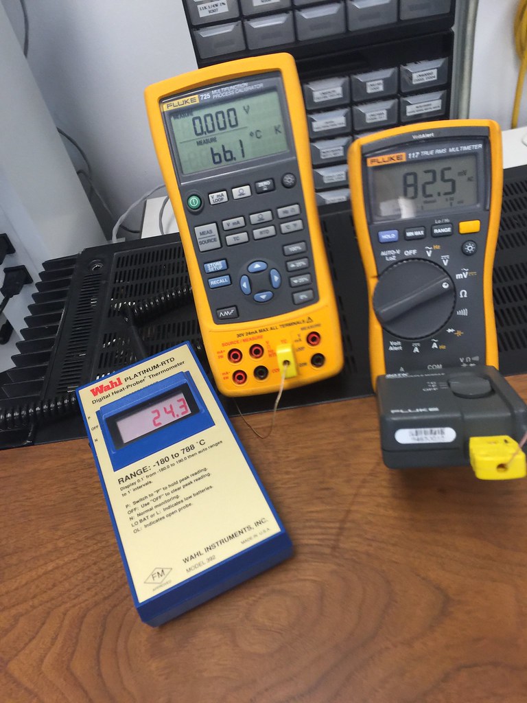
When I flipped the unit back over and removed the bottom cover I noticed that the thermocouple that I had installed had come off. So I repeated the test, this time making sure the TC did not come off. I also put another TC on the circuit board in a blank spot to see how hot it was getting.
The picture shows the results:
The reading on the left is the ambient room temp, the middle is the board temp and the right is the transistor heat sink temp. All temps in deg C.
So I decided that I would move the other two heat sources to the amp heat sinks and be done with it.
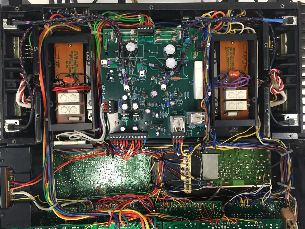
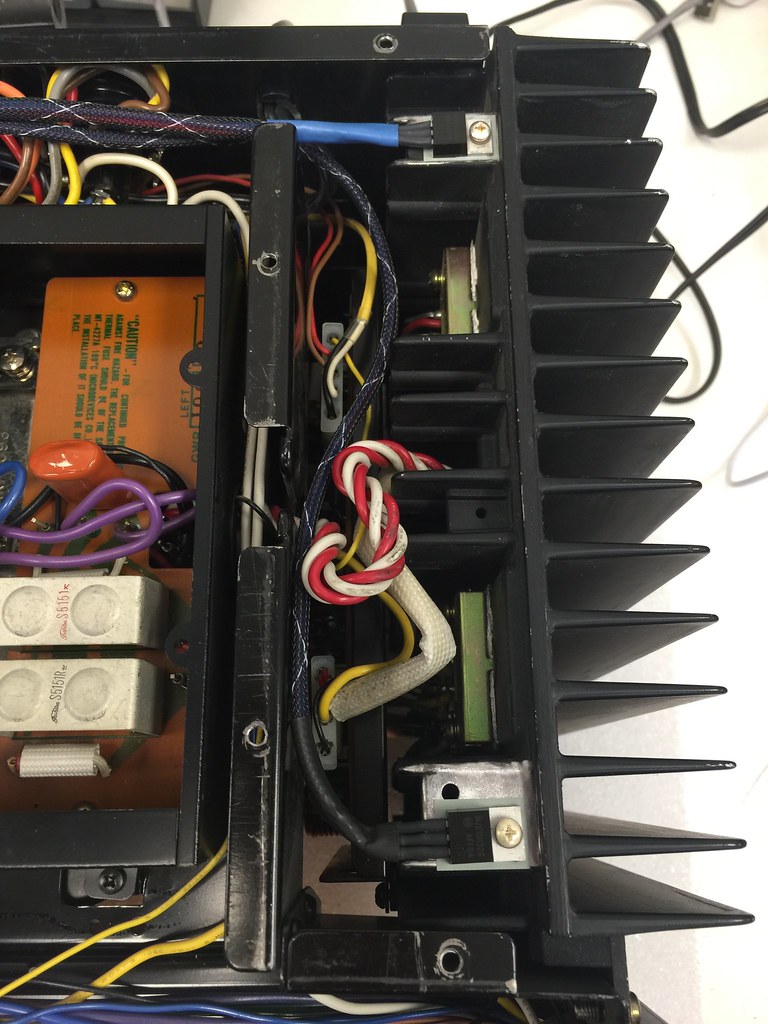
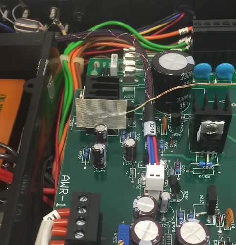
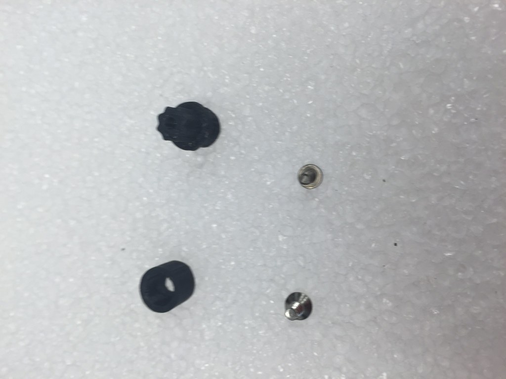
As the final mod I wanted a better way to hold the board in place. The plastic stand off's that came with the receiver were broken so we fashioned up a new system and 3D printed it. It's a bit hard to see in the pictures but it consists of two parts that are held together with a screw. The upper part has a star shaped shoulder that fits into the existing hole in the receiver, with a cap on the back side held in place with a screw. It's kind of tricky to install. Once in place there is a plastic standoff with a threaded hole in it. You mount the board in the usual way and then just screw the corners down.
When I flipped the unit back over and removed the bottom cover I noticed that the thermocouple that I had installed had come off. So I repeated the test, this time making sure the TC did not come off. I also put another TC on the circuit board in a blank spot to see how hot it was getting.
The picture shows the results:
The reading on the left is the ambient room temp, the middle is the board temp and the right is the transistor heat sink temp. All temps in deg C.
So I decided that I would move the other two heat sources to the amp heat sinks and be done with it.
As the final mod I wanted a better way to hold the board in place. The plastic stand off's that came with the receiver were broken so we fashioned up a new system and 3D printed it. It's a bit hard to see in the pictures but it consists of two parts that are held together with a screw. The upper part has a star shaped shoulder that fits into the existing hole in the receiver, with a cap on the back side held in place with a screw. It's kind of tricky to install. Once in place there is a plastic standoff with a threaded hole in it. You mount the board in the usual way and then just screw the corners down.