SX-780 project: relay question - resolved

merlynski

Curmudgeon Electronicist
I am working on an SX-780 that I had happily playing in my motor vehicle (hobby) repair shop for many years. It began having a flaky left channel, then quit completely. I put in an SX-650 I had on hand as it replacement.

I am now in the middle of the SX-780 repair. Somebody in the past botched the pcb repair at the relay solder pads.

relaybefore.JPG

I removed the relay to see the damage better:

relayremoved.JPG

Then I did some clean up and removed a bit more of the solder mask.

relaycleanup.JPG

The case is broken on the old relay so I am going to replace it anyway, my question is

Is the Omron (Mouser 653-my4-02-dc48) still the best choice for the SX-780 protection relay?

Thanks in advance for your help
 
That appear to be the correct part (with pins instead of lugs) and the NC contact pins will have to be removed to fit the PCB.

You might want to look at Keystone 534-23 or 534-25 (longer) eyelets to provide a good connection point for the relay pins and assist in repairing the damaged traces.
 
That appear to be the correct part (with pins instead of lugs) and the NC contact pins will have to be removed to fit the PCB.

You might want to look at Keystone 534-23 or 534-25 (longer) eyelets to provide a good connection point for the relay pins and assist in repairing the damaged traces.

Thanks for replying!

I like the eyelet idea, we used them for similar repairs in the factory I worked in years ago. The eyelets are cheap, but the seating/rollover tooling is $724.00 from mouser :mad:. In my experience the eyelets split instead of seating properly if you don't use the right tooling. Do you have a better source or idea for the tooling? What do you use? :dunno:
 
I use an anvil post and bull-nosed pin punch (and a very light hammer). It gets a little tricky at times supporting the board and aligning everything with your fourth hand, but can be done.

If they split on the top side it isn't a major issue so long as they are staked in place. Solder will fill the split on the first pass anyway.

I ordered the relay and some of both sizes of eyelets.
I have seen it done many times, done it a few times myself, years ago where I worked. It is a bit tricky. :rolleyes:
Where did you get your post and punch?
 
Here are some pictures of the repair in progress. I got some copper tape with conductive adhesive. Pre-trimmed it with scissors to close to the right shape, stuck it down, pressed it down firmly with an eraser, pierced it through, then seated the eyelets. Once the eyelets were seated I trimmed the edges with a sharp blade, pressed it down again with the eraser and inserted the relay through the eyelets. Soldering the relay and flowing some solder over the tape where it overlapped the original traces completed the repair.
DSCF0717.JPG DSCF0719.JPG DSCF0721.JPG DSCF0727.JPG
The transistor that controlled the relay was bad also, replaced it with a KSC2690A from Mouser. This completely resolved the relay problems with this unit.
 
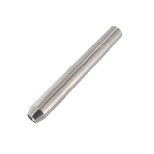
That looks like a good recovery. It was thoughtful of you to document the process and share the photos. Most often when involved in something like that, I don't bother to stop what I'm doing and pick up the camera for documentation. The punches I use were made from Ace drill rod and bar stock. That anvil is one made for setting tubular rivets in textiles, like this:

TLRHS47_1__76635.1458921308.315.315.jpg
 
One of these days I will write up the whole cleanup and repair, as it was a gift for my son's wedding. I also put in the STK replacement/upgrade modules Rcs16, Hbrown (and others) came up with. Parts of it are already in other threads . . .

EDIT: more info
 
Last edited:
I have a couple sets of those modules waiting to be installed in the next suspect. Fortunately, all of my 780s (I believe 5 or 6) are working well on the originals or the aftermarket replacements installed during rework. All indications are that those modules are the final solution to the STK problem, and probably for more units than the 780 and other 50W amps.
 
I'd like to come across another dead 780, I have some ideas for further customization and heat management I would like to try. I have another set of boards and parts on hand already.
 
Last edited:
Back
Top Bottom