sx-939 static

ok, I'm following this fine, and have the manual. When it says dmm on 50 and 44 this means using a jumper wire to get a reading across both pins at the same time right?

NO JUMPER WIRES!!!!!!!!!!!!!! that's a zapppppppppp!!!!!!!! <worried, not angry>

Red dmm lead to pin 50

Black dmm lead to pin 44.
 
You're doing pretty good winging it.

Dealing with an uncooperative meter etc.....

And there's NO SUCH THING as a dumb question.....

I'M glad you asked.... :D

When in doubt, ask....
 
I'm gonna come back to it tonight with a clearer head. I may be confused with the manuals diagram which VR is which. If I look at like it shows from the top of the unit those vr pots are upside down, adjustments from the bottom of the unit. When I checked with pin 10 and grd. it keeps bouncing from 0.00 to 0.43 and would stay at 0.00. maybe I had the meter set wrong, or I'm adjusting the wrong VR pot. I am reading DC voltage correct? and when it says to have nothing connected to inputs does that include the two metal jumper pins?
 
Zero volume is usually ok. leave the jumpers from pre-out to amp-in connected... gives them a path to ground instead of the floating input acting like an antenna....

You can measure the offset voltages at the speaker terminals, it's usually easier... (as long as the protect relay engages, connecting the amplifier to the speaker terminals).

The meter may be reading a very very low voltage, is it an auto-ranging meter? for example, do you just switch it to DC volts?, or do you select voltage - like 2 volts, or 20 volts or 200 volts DC?

Or post either:1. the maker and model, or 2. a picture and I'll figure it out.

Yeah, those pots are fun, they are exactly the same distance from the front and back of the board, making THAT description useless...

The two pots (offset voltage adjust) closest to the wire connections for the two bias diodes are the pots used to adjust the voltage to zero (measured in millivolts) at the speaker terminals. They should be marked with a 10K as part of their alphabet soup.

The other two (idle current adjust) pots are kinda interfered with by the connections to the power output transistors (pin 51 on one channel and pin 39 on the other) , and should be marked 100, these are the pots used to adjust to 50 millivolts (0.050 volt) between pins 50 and 44 (one dmm lead each), and for the other channel for 50 millivolts (0.050 volt) between pins 38 and 32.

Hopefully this should be clearer than mud.
 
Last edited:
I have both types of DMM's - one is the auto-range (AC and DC) the other I can select like you said DC 2, 20, 200 volts. If I use the selectable one, would I set it to 200v? And yes, the protection relay is clicking on after about 4-5 sec. of power on.
 
checking it again (offset voltage adjust) with speaker terminals or on the pins I get a reading (set to mV DC) before I even turn in on of 002.0 and it keeps going up 002.1 and so on.
If I turn it on and try to adjust VR1 I don't see any difference in the reading. It just keeps raising. :scratch2:

after 10 min. (still connected to dim bulb) if was as high as 25-26mv starting to slow...and I heard the protect relay click on and off a couple times during this but no matter how much I turn VR1 the reading aren't affected.

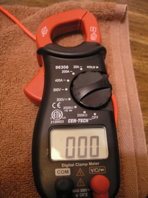
and the other meter set to DC 300v only shows 000 and never changes maybe 001 and then back to 000.

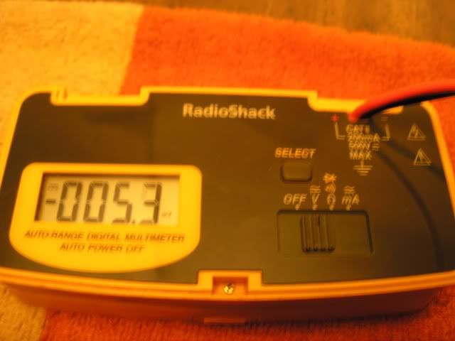
So I don't know which meter to use at this point. Maybe you can see something I don't in these pics...

P1010102.jpg


P1010105.jpg
 
Last edited:
it's blurry, but i think the Radio Shack one is reading -005.3 millivolts (mv) which is good, that's 0.0053 volts

while the cen-tech just doesn't appear to have the sensitivity to read millivolts.

And could you be adjusting one channel while reading the other???? :D
 
it's blurry, but i think the Radio Shack one is reading -005.3 millivolts (mv) which is good, that's 0.0053 volts

that is what it is reading but it keeps going up -005.4 and so on, after about 10 min. it showed about -0025.0 but after trying to adjust the pot(s) and not seeing a change should I be worried that something else is still wrong?

while the cen-tech just doesn't appear to have the sensitivity to read millivolts.

correct, it doesn't

And could you be adjusting one channel while reading the other???? :D

yep, I thought about that, but adjusting either does the same thing turned fully in both directions does nothing. Does thing mean I should search out a better DMM? I could probably take it to a friend who should be able to help this weekend.
 
after along break...I finally got around to borrowing a better DMM and got the readings to register with turns of the pots. But after being on for about 15 minutes warm up time the unit kicks back on the protection and the sound goes out. It looks like I have more components to replace.
 
When it is in protection, some voltage measurements are needed to figure out why and where...

Be ABSOLUTELY careful not to short any pins together.

All voltages are referenced to a bare metal chassis ground with the black DMM lead.Probe with the red lead and the probe completely insulated except for a tiny portion of the tip of the probe.

On the protection board awm-062 measure the DC voltage on pins:
p2 -13v
p3 0v to +/- 40v amp out from one channel
p4 0v to +/- 40v amp out from other channel
p10 +35v
p9 +10v or +35 depending....

measure the AC voltage on pin 12 (7.5v ac)

Then on the awh-030 amplifier board check/measure these dc voltages:
p1, p2 -42v
p4, p5 +35v
p7, p8 +45v
p10, p11 0v amp out
p14 +45v
p15 -45v
p16, p17 -42v
p19, p20 +35v
p22, p23 +45v
p25, p26 0v amp out
p29 +45v
p30 -45v

then if the voltages above ( except the amp out voltages p3,p4 protect, p10,11,25,25 on amp) are ok, yet the voltage on pins 10 & 11 or pins 25 & 26 is greater than 0.1 volt read all the DC voltages on pins 31 through 54 , these are all pins on the "back row" of the board and are connected to the transistors.
 
Last edited:
mark, I've been pulled away by some other "life issues" recently, but finally dusted this off and opened it back up and got it in protect mode with these readings...but before it would go into protect it gave me alot of loud crackling static in the left channel (for about 10 minutes) then it went away (slowly) and then it started popping in and out of protect.

protect bd (awm-062)

p2 = -13v
p3 = 0v
p4 = 0v
p10 = 36v
p9 = 36v
p12 = 7v


amp bd (awh-030)

p1, p2 = -43v
p4, p5 = 35v
p7, p8 = 46v
p10, p11 = 0v
p14 = +49v p15 = -49v
p16, p17 = -43v
p19, p20 = 36v
p22, p23 = 46v
p25, p26 = 0v
p29 = +49v p30 = -49v
 
Last edited:
What have you done so far?

so far I've put the diode across pins 9 and 10 on the protect board.

and replaced the following components on the amp board (awh-030)

Q1, Q2, Q3, Q4, Q5, Q6, Q7, Q8, Q9, Q10, Q11, Q12

C1, C2, C3, C4, C5, C6, C11, C12
 
I'm confused by the description, there is NO change in the symptoms?

also i goofed slightly, i meant pin 1 of protect not pin 4 for the reading.

no more crackling, but after 15 minutes it goes into protect?

get any extra transistors for the amp work? sounds like the relay driver transistor on the protect...

checking......

yup: i did mention those parts, but i haven't yet checked in stock...
The protection is awm-062, the SAME as in the 1010. most protection is the same, 4 caps, 2 transistors and a diode added.

Q6
512-KSD1616ALBU to-92 ecb x60v 1a 0.75w 160mhz 135-400hfe $0.09
edit 2/7/201 this 1616 is 60v not 160 but is ok here

Q7
512-KSC2690AYS to-126 ecb 120/a160 1.2a 20w 155mhz 35-320hfe $0.40
add diode to pins 9(unbanded end) & 10(banded end) going off the board
512-1n4004 conventional rectifier 1a 400v $0.06 ea

c1 c2 0.22uf unk volts (0.22uf/50v non-polarized film cap)
598-DSF050J224 $0.14? ea
c3 c4 330uf 6v (330uf/10v)
647-UPW1A331MPD $0.20 ea
c5 4.7 25 (4.7uf/50v)
647-UPW1H4R7MDD $0.12 ea
c6 100uf 16v(100uf/50v)
647-UPW1H101MPD $0.22 ea
 
Last edited:
It's still going in and out of protect every few seconds but I couldn't remember if I heard crackling static back then but I'm sure it's in the left channel.

p1 = bounces between 0v and -1v

the crackling starts when you turn it on and sometimes clears up after few min. but not always. and this time it started going into protect within the first 5 minutes.

its been awhile and I'm not real sure, but I don't think I changed any components on the protect bd. except for that diode added.

So, your saying I should have changed those trans. and caps on the protect?

I'll see if I have enough transitors left.
 
Update: I finally got some parts ordered for the AWM-062 protect bd.
and replaced the 6 caps and 2 transistors last night.

The unit now powers on and stays on! no clicking and going into
protect mode. No loud cracking/popping!

It ran for over an hour sounded good. I do still however have a slight bit of
low level static coming from the left channel.

any thoughts Mark? :scratch2:
 
memory gone, (did a 939 on saturday, memory wiped) what replaced in amp, static on fm, or phono, or aux?

if pre-power jumpers pull them to see if static goes away, swap left/right at pre-power and see if it moves, if so, is control amp & a725/a726's in it..

also phono amp may have a725/a726's in it.

ksa992 is replacement...
 
ok, the low level static was coming out of aux, and fm, didn't check phono and when I switched the pre-power jumpers I heard the static in each channel.

I went ahead and replaced Q1 and Q2 on the control amp board with KSA992's.

Now when powered up it seems the static is gone, BUT....now if you turn the volume up to about 3 or more it starts clicking back and forth rapidly.???

maybe I should put back the old transistors (Q1, Q2) on the control amp and just live with the low level static? I mean it ran all night without clicking into protect at all with moderate to high volume. (see my last post above) :scratch2:


This is my progress of components changed so far....

amp board (awh-030)

Q1, Q2, Q3, Q4, Q5, Q6, Q7, Q8, Q9, Q10, Q11, Q12

C1, C2, C3, C4, C5, C6, C11, C12


protection board (awm-062)

Q6, Q7 (transistors)

C1, C2, C3, C4, C5, C6 (caps)


control amp bd (awg-027)

Q1, Q2
 
Back
Top Bottom