sx-939 static

No mention made of power supply work, relay runs off of +35v, pin 5 of power supply - it could be falling down on the job. Q3 through R18 (33 ohms) drives it = watch the +35 or check it when it goes into protection.

Q3 is a itty bitty 2sc1318, a
512-KSC2690AYS to-126 ecb 120/a160 1.2a 20w 155mhz 35-320hfe $0.40
may be more appropriate to the situation.

also check the -13v and the 7.5v AC to see if they is still there while it is in protection.

sorry about the mix up about what had been done and if any frustration showed through it is about non AK matters and sorry if it got loose.

no problems Mark, I understand you really got your plate full as of late.

ok, when I turn it on now I get the click at about 3-5 sec. and I'm getting 33.7v and then after a awhile it trips and it jumps up to 35v and then back to 33.7v

Should I change it out anyway? what about Q2? it looks like another 2sc1318?

also, where do I check the -13v and 7.5v AC ?

On the Protection Board here is a previous post from this thread from Mark
When it is in protection, some voltage measurements are needed to figure out why and where...

Be ABSOLUTELY careful not to short any pins together.

All voltages are referenced to a bare metal chassis ground with the black DMM lead.Probe with the red lead and the probe completely insulated except for a tiny portion of the tip of the probe.

On the protection board awm-062 measure the DC voltage on pins:
p2 -13v
p3 0v to +/- 40v amp out from one channel
p4 0v to +/- 40v amp out from other channel
p10 +35v
p9 +10v or +35 depending....

measure the AC voltage on pin 12 (7.5v ac)

Have you replaced any thing on the power supply board caps etc.... ????
 
Last edited:
ok, borrowed yet another multimeter and this one is registering with the turn of the VR pots...

DC offset - was able to nail down 0.00mv for both L & R

Idle Current - was only able to go as high as 00.3mv and the pots wouldn't turn any further in that direction. I take it this is 30mv

Is that bad I wasn't able to reach 00.5mv or 50mv ?

DMM was set to 200v DC - and the unit was warmed up for 20 min.

1 Volt = 1000 mv

Something is not right here with the idle current.
Does your meter have a 200 or 300 mv range setting?

Is it auto ranging??

Your are trying to reading mv so 200 volt range is to high.

So if it read .3 on 200v it is not 30 mv it is 300 mv

And yes it would get hot.
 
Last edited:
On the Protection Board here is a previous post from this thread from Mark


Have you replaced any thing on the power supply board caps etc.... ????

Thanks for your help goat!

I'm getting -12.9v on p2 (in and out of protect)

and 7.1v on p12 (in and out of protect)


Nothing has been replaced yet on PS board...
 
Last edited:
1 Volt = 1000 mv

Something is not right here with the idle current.
Does your meter have a 200 or 300 mv range setting?

Is it auto ranging??

Your are trying to reading mv so 200 volt range is to high.

So if it read .3 on 200v it is not 30 mv it is 300 mv

And yes it would get hot.

now this would make sense why I couldn't get the VR pot to turn anymore to reach 50mv...(according to my amateur logic of reading mV specs) :)

I'm lucky I even found a DMM that registers when turning the pots...(I've tired 2 others with no luck)

It's not auto-ranging nor does it have a mv setting.

I can go down furthur setting the DMM to 20v or 2v DC

If I use the 200v setting then I would need to get a reading like .05v ?

Could this be why it's jumping in and out of protection...having idle set @ 300mv??

Or, am I looking at having to rebuild the power supply? it still has alot of those old sky blue caps.


just strange that it ran for 2 hrs. last night solid and now it's popping in and out after being on for 1-2 minutes.
 
Last edited:
tonight I'm back at it...set my DMM to lowest setting 2v DC

and receiver has been on for about 20 min.

with idle current backed off to a reading of .050v DC

switch over to 20v DC and I get 0.05v DC

and DC offset as close to 0.00 as I can get both.


crossing fingers that it doesn't trip the protect on...

And...it's still going in and out of protection, but maybe not as much as last night.
 
Last edited:
now this would make sense why I couldn't get the VR pot to turn anymore to reach 50mv...(according to my amateur logic of reading mV specs) :)

I'm lucky I even found a DMM that registers when turning the pots...(I've tired 2 others with no luck)

It's not auto-ranging nor does it have a mv setting.

I can go down furthur setting the DMM to 20v or 2v DC

If I use the 200v setting then I would need to get a reading like .05v ?

Could this be why it's jumping in and out of protection...having idle set @ 300mv??

Or, am I looking at having to rebuild the power supply? it still has alot of those old sky blue caps.


just strange that it ran for 2 hrs. last night solid and now it's popping in and out after being on for 1-2 minutes.

Do you have a Dim bulb Tester?
If not you need one to build one

The pots you adjusted to set the bias are the turned fully CW I am pretty sure this is the case to increase bias If so turn them back to full CCW

And yes if you ran this thing with the bias fully turned up you could have damaged the pre diver transistors or it could cause it to go in to protect.

It would be a good idea to replace the caps on this board. So get a list of the caps on the board. Follow the cap list format Mark uses and we will get you some part numbers.

Do you have the transistor Mark asked you about?

512-KSC2690AYS to-126 ecb 120/a160 1.2a 20w 155mhz 35-320hfe $0.40

I am trying to help out so we need to get on the same page.....


Yes, I do, and have been using a Dim Bulb Tester....

and your also correct they were fully turned to CW and it ran for about 2 hrs. this way...I started tonight by turning it back fully CCW...

ok, I do have that transistor mark said would work better, what about the one next to it? it's the same value (Q3 as well as Q2)

512-KSC2690AYS to-126 ecb 120/a160 1.2a 20w 155mhz 35-320hfe $0.40

also so we are on the same page your talking about replacing all the caps on the power suppy board ?

and you said I could have damaged the pre-driver transistors? are they also on the power supply board?
 
Last edited:
Yes, I do, and have been using a Dim Bulb Tester....

and your also correct they were fully turned to CW and it ran for about 2 hrs. this way...I started tonight by turning it back fully CCW...

ok, I do have that transistor mark said would work better, what about the one next to it? it's the same value (Q3 as well as Q2)

512-KSC2690AYS to-126 ecb 120/a160 1.2a 20w 155mhz 35-320hfe $0.40

also so we are on the same page your talking about replacing all the caps on the power suppy board ?

and you said I could have damaged the pre-driver transistors? are they also on the power supply board?

Just to check the adjustments where done NOT USING the DBT right?

Q2 does not need to be replaced unless you are having issues with the phono board.

Just replace Q3


If it is not going into to Protect you did not damage the pre drivers on the amp board.

This thread has gone on for a long time. What is the status of the unit working?
sounds good?

If I was doing this repair I would have recapped the Power Supply and Protection Board regardless.

So the question to you is what do you want to do.

If you want to finish doing a total recap list what parts you need for each
board and we can get a Mouser parts list going.

Right, NOT USING the DBT - just after making changes and first powering up.

ok, will replace Q3 only today.

The unit works, and sounds great...BUT it IS still going into protect.

I have replaced caps and transistors on ALL boards except the tuner and power supply. I will get a list together I guess to replace all the caps on PS.

Now, about those pre drivers on the amp, can you point out where they are for me? and can I test them to see if they are damaged? thanks.

I just want to get this thing to work without going into protect, I will do whatever is necessary, not going to give up now.

Good news on the caps get the list together for the PS do not worry about the tuner.

What has been replaced on the power supply board anything?


Change out that transistor it is the relay driver transistor and it may very well be weak and causing it to go into protect.

As far as what are the pre drivers / drivers they are on the amp board and AWH-030
Q5 Q7 / Q9 Q11

Q6 Q8 / Q10 Q12

If you had an issue I would have expected the magic smoke to have came out. But look at the emitter resistors and see if any look burnt.
R37 R39
R38 R40
 
If it stays in protect, (instead of tripping for a few seconds and coming back on) then you CAN make some voltage measurements ON the protect board awm-062, WHILE it is in protect. They will pinpoint the problem. THEN we fool with the amp or power supply. We are locating an intermittent, and starting at the best place to spot it.

they are:
pin 10 (35 volts, power from power supply)
pin 2 (-13 volts, power from power supply)
pin 12 (7.5v AC!! turn on / turn off sensing)
pin 9 (35v relay off, 10v relay operating, pulled in)
pin 1 (0.000v) amplifier output
pin 3 (0.000v) amplifier output

now some harder readings:
emitter, base and collector readings of q7 the 2sc1384
the voltage on the minus side of C5: 4.7uf (-5v dc)

the single voltage at the point where Q5 base and d5, d6, d7 anodes (non-banded ends) are all connected together (+20v ok, much lower if protect is being triggered)

the voltage at the cathode (banded end) of D5
the voltage at the cathode (banded end) of D6
the voltage at the cathode (banded end) of D7

if d7's (or d6's or d5's) banded end is at a LOWER VOLTAGE than the non - banded end - THAT is the circuit triggering the protect.

If so, D5 is overcurrent detect, so Q1 and Q2 could be replaced, their caps checked and diodes checked in their "mini circuits" around them.

If D6 or D7 is the trigger, that's the DC offset voltage detect circuit, and if the pin 1 and pin 3 voltages are under 0.6 volts, then Q3, Q4 get replaced.

Q1,Q2 are ksc2310
q3 and 14 can be ksc1845
Q5 also can be ksa992

but q6, if original should be ksd1616, as it takes a pretty heavy shot of current from C6 when turning off.

guys, talk him through finding those points. I'll check back later. Thanks.
 
Last edited:
it is going to next to impossible to get a reading...let alone all those readings since it's intermittent and when it does go into protection it only lasts 1-2 sec.

so, my thought is to just go ahead and replace Q1, Q2, Q3, Q4, Q5 now since I have parts. I replaced Q6, Q7 along with all 6 caps last week on the protect board.

one thing I noticed is Q1, Q2 (original transistor) are installed as BCE - so is this another misprint in the manual like the 2sa725 ?

sound like a plan ? it can't hurt right?

also goat67, the only thing I've replaced on the PS board now is Q3 as of today.

Mark, also you mentioned above: emitter, base and collector readings of q7 the 2sc1384....was this in reference how to check it? because I installed it ECB ??
 
Last edited:
we are looking for large unmistakable deviations in voltage.

ignore the original's orientation, use the symbol on the board and replacement's datasheets. And test it first before installing.

you could disconnect Q5, Q6 & Q7's cathodes and see if that stops the protection triggering. If so, we then have narrowed it down a bit.

then reconnect either Q7 or as a group Q5 & Q6 and see if the protection starts triggering again.

if you have the transistors and they are installed in the correct orientation, there is no problem about shotgunning the protection circuit. The risk I usually avoid is 7 chances to get it wrong, while the chances of failure are in this order: Q7, Q6, (q1,q2), (q3,q4), q5

as for the q7 readings, i just wanted the three readings , and base is highlighted as the most important reading. the order I posted is not significant in this case, sorry. I usually say three voltage readings on Q7, but didn't want to leave room for misinterpretation.
 
Fixed!!

well, I had the transistors, so I decided to try the shotgun approach this time...and replaced Q1, Q2, Q3, Q4, Q5 - and then after checking my work, I fired it up and to my surprise the relay never clicked after few seconds. :scratch2: so at this point it's in protect, I might as well get those readings.
so below in bold is what I got, not sure I tested Q7 the correct way.


If it stays in protect, (instead of tripping for a few seconds and coming back on) then you CAN make some voltage measurements ON the protect board awm-062, WHILE it is in protect. They will pinpoint the problem. THEN we fool with the amp or power supply. We are locating an intermittent, and starting at the best place to spot it.

they are:
pin 10 (35 volts, power from power supply) 35.3v
pin 2 (-13 volts, power from power supply) -13v
pin 12 (7.5v AC!! turn on / turn off sensing) 7.0v AC
pin 9 (35v relay off, 10v relay operating, pulled in) 35.5v / 8.2v
pin 1 (0.000v) amplifier output 0.02v
pin 3 (0.000v) amplifier output 0.02v

now some harder readings:
emitter, base and collector readings of q7 the 2sc1384
the voltage on the minus side of C5: 4.7uf (-5v dc) 0.00 / 0.L / 0.00

the single voltage at the point where Q5 base and d5, d6, d7 anodes (non-banded ends) are all connected together (+20v ok, much lower if protect is being triggered) 3.29v

the voltage at the cathode (banded end) of D5 2.96v
the voltage at the cathode (banded end) of D6 2.77v
the voltage at the cathode (banded end) of D7 2.78v

if d7's (or d6's or d5's) banded end is at a LOWER VOLTAGE than the non - banded end - THAT is the circuit triggering the protect. non-banded: d5,d6,d7 = 3.29v

If so, D5 is overcurrent detect, so Q1 and Q2 could be replaced, their caps checked and diodes checked in their "mini circuits" around them.

If D6 or D7 is the trigger, that's the DC offset voltage detect circuit, and if the pin 1 and pin 3 voltages are under 0.6 volts, then Q3, Q4 get replaced.

Q1,Q2 are ksc2310
q3 and 14 can be ksc1845
Q5 also can be ksa992

but q6, if original should be ksd1616, as it takes a pretty heavy shot of current from C6 when turning off.

guys, talk him through finding those points. I'll check back later. Thanks.

I started looking over my work again on the protect board and wouldn't you know...I put Q3, and Q4 in wrong (base & collector switched!) Doh! :screwy:

I bet that is why it stayed in protect.

I took them out and installed them this time correctly and this beast has been working flawlessly since, it ran all night without clicking in and out.

I'll run it and monitor it to see how it does today, but really hoping that was it.

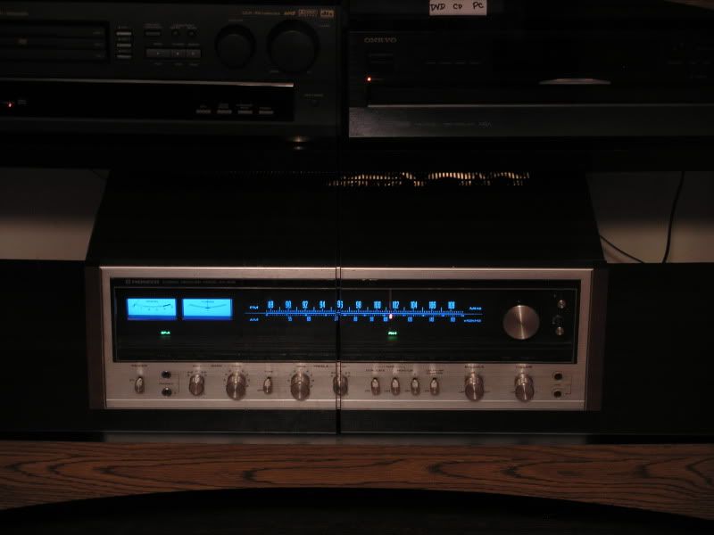
Mark once again you nailed another one! your help along with Echowars and goat67 has been a lifesaver! another vintage receiver lives on. :thmbsp:

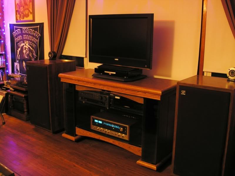
Had to get a new stereo cabinet to hold it too, since it was too wide to fit in my old stackable cabinet from the 80's.

These speakers sound completely different (for the better) now with this Pioneer compared to my old Sony receiver ever did.

No WAF to worry about here in my house! :banana:

P1010031.jpg


P1010038.jpg
 
Last edited:
well, I had the transistors, so I decided to try the shotgun approach this time...and replaced Q1, Q2, Q3, Q4, Q5 - and then after checking my work, I fired it up and to my surprise the relay never clicked after few seconds. :scratch2: so at this point it's in protect, I might as well get those readings.
so below in bold is what I got, not sure I tested Q7 the correct way.


I started looking over my work again on the protect board and wouldn't you know...I put Q3, and Q4 in wrong (base & collector switched!) Doh! :screwy:

I bet that is why it stayed in protect.

I took them out and installed them this time correctly and this beast has been working flawlessly since, it ran all night without clicking in and out.

I'll run it and monitor it to see how it does today, but really hoping that was it.

Mark once again you nailed another one! your help along with Echowars and goat67 has been a lifesaver! another vintage receiver lives on. :thmbsp:

Had to get a new stereo cabinet to hold it too, since it was too wide to fit in my old stackable cabinet from the 80's.

These speakers sound completely different (for the better) now with this Pioneer compared to my old Sony receiver ever did.

No WAF to worry about here in my house! :banana:

P1010031.jpg


P1010038.jpg

AWESOME! Great work....a happy ending:music:
 
congrats on a great job, and a great thread.

I have anon functioning 939, and this is going to be a huge help in getting started on my first restoration project.

thanks everyone!
 
well, things have been working fine about 2 months now and after being on for 4-5 hours in an evening I'm getting small amounts of static coming out,
even with volume turned down from Phono or Aux positions and when both jumpers are pulled out, I don't hear it.

So, would I need to look at the control amp board? the only transistors I replaced on it was Q1 and Q2 (sa725s).

I think there was about 6 more sc1312s, maybe I should get back in there and replace these and while I'm at it do all the caps too.

the only other thing I've noticed is my FM signal is now distorted, when I started working on this it sounded great, at least while monitoring with headphones.
 
Last edited:
Back
Top Bottom