Technics SU8600 no relay click on

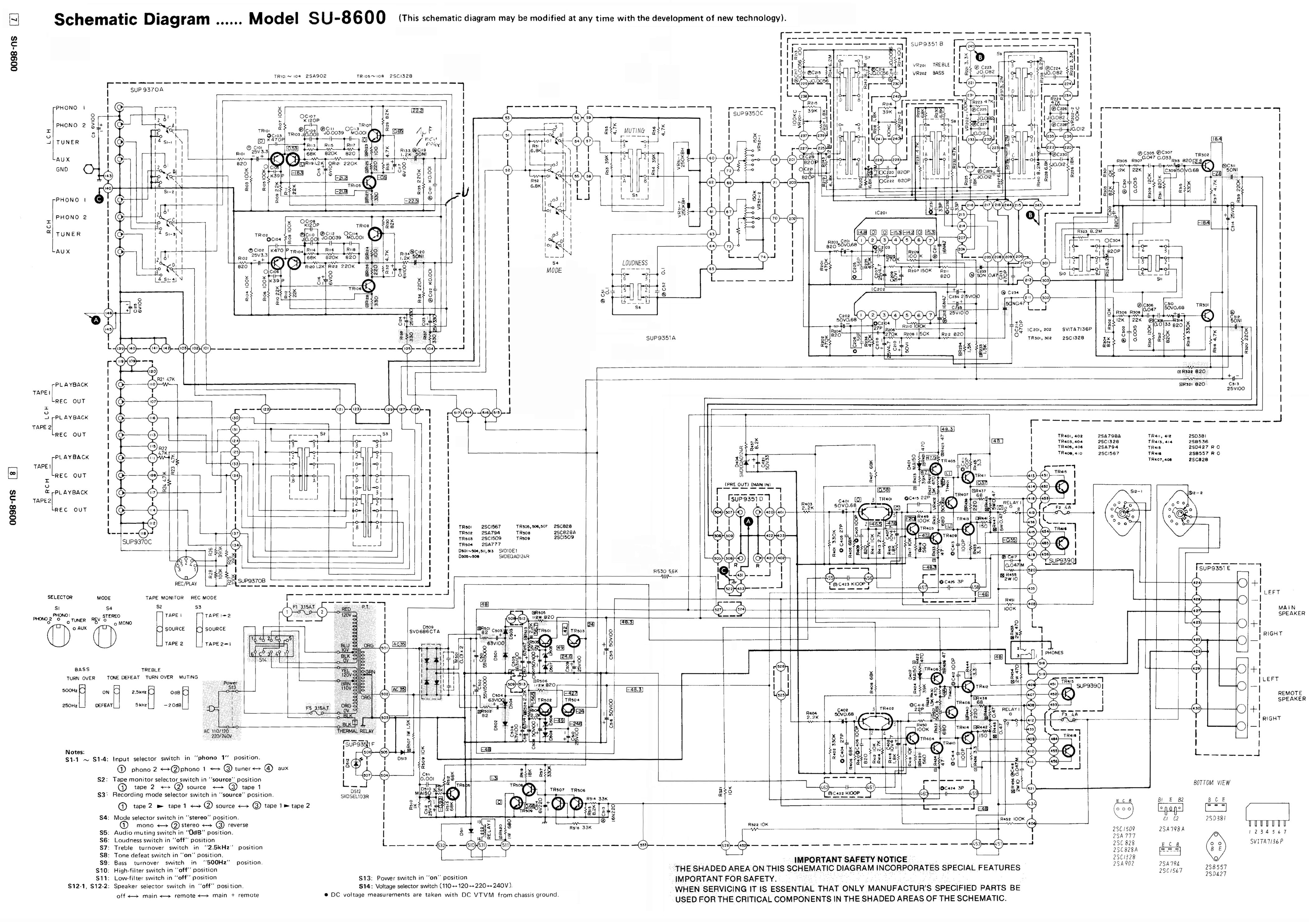
I am trying to get one of these going. All I get is the red light comes on after powering it on, no relay click and thus no output. I also found a great response and description from EW on the protection workings from a few years ago. I followed that and none of the components tested bad. Calling in the troops, I need some assistance please.
 
Is the red light blinking?

Are the main and pre amp connected at the back panel?
 
Well, if the red light is steady, it is not in protect.

And the relay then not working is strange. It might be broken, but that is very very rare. Are you sure it is not working? Perhaps you just don't hear it?

If indeed it is not working the thing needs more attention, measuring voltages and compare these to what is mentioned in the service manual, perhaps using a scope to follow the signal.
 
When powered on no click noise and it has a clear cover on the relay, no visual movement.
I have the service man, what would be the best starting point?
No visual burnt or exploded components. Looks to be in decent shape.
 
How skilled are you, when it comes to using the necessary equipment, multimeter, scope?

I'd start at measuring the voltages at the coil side of the relay. Then the voltages at the loudspeaker channels of the relay, the amp side, not the speaker output side (these voltages might be in mV). All voltages related to ground.
 
For the rest to follow along:

TechnicsSU-8600Schematic.jpg
 
Jeromach, I have some equipment, no scope. I have fixed a few units. I have 47.5 on pin 14 and 5mv on pin 12
Watthour, I have 0 on pin 533.
 
Jeromach, I have some equipment, no scope. I have fixed a few units. I have 47.5 on pin 14 and 5mv on pin 12
Watthour, I have 0 on pin 533.

Is that pin 14 on the protection relay? And pin 12? It appears that pin 13 on the relay is the more critical measurement. No measurable voltage at pin 533 on the board should be correct to allow the relay to close.

Measuring the voltage across C514 would also be helpful.
 
C514 needs to charge through R517 to turn on TR508/509. TR506 and TR507 are the left and right channel overvoltage protection, and TR505 is the AC power sensing. Any of those will discharge C514 and shut off TR508/509 (and the relay) if they are not happy. If either of those are shorted, they will also prevent C514 from charging. Since the voltage at pin 533 is reported as 0, and not + or - 0.6V or more, the amps are probably O.K. It may be worthwhile to look into the circuit around TR505 to verify that it is not biased on during normal operation (or shorted E-C).
 
After retesting TR505,506,507,508 and 509 it seems to me that they all are NG. Please tell me if I am doing something wrong. This is the way I am testing them with a DMM. B-E,B-C,E-B,C-B and C-E. With the positive lead first the readings should be .4 to.9 for the first 2 and then OL for the remaining 3. I have tested new similar ones with proper readings.
Could they all go bad? Is this the protection circuit doing what is supposed to do? With out getting ahead of myself, Could this be the result of shorted outputs?
Really appreciate the help.
 
I would tо be sure. Then you need to switch DMM to 200KΩ and measure +(red) to C or E & - (black) to B.
 
Removed and tested all TR in the protect circuit. All tested good. Quite a difference in readings. Also I checked D510 and D511, all good.
 
I would personally look next for a shorted cap in the protect circuit. Ie: if a critical one isnt holding a charge it may prevent the relay from closing
 
Yep I was going to go there next. Replaced all caps in the Protect Circuit. No change. Power on , red light , no relay click.
Just for hoots, I may remove the outputs and check them.
 
Back
Top Bottom