The art of amplifier layout & wiring - experience sought...

Blueglow

Eternal Tinkerer
Subscriber
The more amplifier building that I've done, the more that I have progressed to seeing it as an art more so than a science. The science (electrical engineering) part of it is pretty simple to me these days, but the art of it is something I am seeking to master.
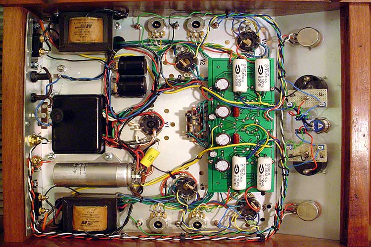
For example when I see a well laid out physical design with right angle wiring like in the attached pictures, I feel a burning desire to slow down and focus on building pieces of art myself. Maybe my issue is I'm more of an engineer than an artist (can't draw to save my life), but I have to believe there is hope...

Looking for any tips or suggestions on how to best layout amplifier design (i get the electrical aspects - input far from power supply, etc) for aesthetics and wire layout. Also, tips on how to make & run these 90 degree wires & leads in such a beautiful fashion are welcomed as well. Would love to learn to do wire wrapping like the old masters did (WE, etc.)

Just trying to take my game to another level.
Thanks,
Mark

rightangle2.jpg
rightangle1.jpg
 
Last edited:
IMO, it's a science to avoid ground loops and cross talk or instability due to coupling. If it looks good, so much the better, but the electrons don't care about that. My neatest builds have been junk, yet some sloppy ones have been superb. There are things that should be twisted, and I don't see that above. There are circuits that should have minimum loop area, which chassis-corner wiring with nice right angles doesn't lend itself to. Learn the science and what you can do with the art will follow.
 
Already know all that stuff, been at this 30 years, trying to taking it from making amps to making pieces of art (that function great as well), probably should have said that.
IMO, it's a science to avoid ground loops and cross talk or instability due to coupling. If it looks good, so much the better, but the electrons don't care about that. My neatest builds have been junk, yet some sloppy ones have been superb. There are things that should be twisted, and I don't see that above. There are circuits that should have minimum loop area, which chassis-corner wiring with nice right angles doesn't lend itself to. Learn the science and what you can do with the art will follow.
 
One trick I have sometimes found helpful is to capture the schematic and use the 'ratsnest' display in a PCB design tool for component placement optimization. This can help quite a lot with physical layout for point-to-point wiring even if you don't plan to create PCB artwork.
 
No experience creating a layout as you've posted above....it is nice looking.

Perhaps some specialty pliers...?

I believe these are jewelry making pliers...

DSC_0662.jpg
 
Practice makes perfect. This is a skill I've also been trying to perfect for quite some time. Stay off the tops of tube sockets and solder lugs where possible, layout for shortest audio path, use a star/bus combo ground system. Go slow and careful when wiring it up. Cut leads to exact length. If you don' like what you just did, cut it out and do it again. Small detail matters. Find someone's wiring layout you like and emulate it. You will quickly learn what works and what doesn't.

As mentioned previous. Artful layout is secondary to good hum free sound. Nobody will care how aesthetically beautiful your wiring is if it sounds bad.
 
with PP amps you have a little more lee way on layout siince the PP OPT will cancel some of the noise in the circuit. But with Single ended it is very critical to have a well thought out layout.
I dunno how you begin your wiring, but i always start with the AC. So, as you mentioned the primary for the PT the leads should be twisted and kept as short as possible. On/off switch and fuse should also be kept as close to the PT as possible. Next is wiring the filament circuit. I like to use solid core either 18 or 20 awg teflon insulated. Solid core wire stays put better than the stranded wire. Chucking the wire in your drill on one end and fastening the other in a vise you can easily twist the filament wires into a tight spiral. There is a lot of info on how to wire the heaters to the tube sockets and layout in your chassis. So, after the filament layout you can then map out the B+ wiring and components, knowing where you can put your components and wiring will be determined by the routing of your filament circuit. Things will follow from that.
I personally have never found out any piece of equipment that was wired nicely AND correctly that had problems from said wiring and layout. If you look at the wiring in Fisher, Marantz, Rogers, Allen amps and mil spec equipment they purposely avoided a "rats nest" approach and purposely used a straight and right angled layout.
 
Last edited:
Form generally follows function when building an amp. Wiring style and layout are the signature of the amp builder. I can appreciate the aesthetic beauty in both the seeming chaos of a "rats nest" as well as a highly ordered design. While there are certainly "ground rules" (pun intended) for building a quiet, functional amplifier, there are a myriad of interesting ways to achieve this.
 
Gotta say I'm not all that much into the aesthetics ... as mentioned, it's all about results. Long as I got no noise or ground loops, I'm happy.

One handy tool to have is an old hand drill for twisting wires. One end of the wires in a table vise, and chuck up the other end for a nice even twist. That's your best bet for keeping signal wires quiet. I've got some wicked long runs in this build with dead quiet out the other end.

wiring-final.jpg


PS ... I did go through several versions of the meter circuit, including a couple after snapping this pic. I did eventually get it right and cleaned up the rats nest there ...
 
Its just an observation, but in the OP pics it looks like the builder had used breadboard wire shaping tools. I bet he is the type of guy who has breadboarded an entire television. :)

He might have a bunch of different size right angle blocks/tools on the bench to measure and form stuff on the fly. I have a resistor bender tool for stuff like this.

I've always wanted to build like this, but I've mostly only rebuilt stuff. i am hoping to break ground on some mono blocks soon and see if I have any chops in the home brew department. I'm slowly making my way through drilling holes and overall design, I can't really afford to screw up any more chassis. Metalwork is the biggest pain in my rear end.
 
One handy tool to have is an old hand drill for twisting wires. One end of the wires in a table vise, and chuck up the other end for a nice even twist. That's your best bet for keeping signal wires quiet. I've got some wicked long runs in this build with dead quiet out the other end.

wiring-final.jpg
Generally your 'best bet' for keeping signal wires quiet is shielded cable, which would alleviate the long runs, as you have pictured here.
 
Two equally famous guitar amps:
2812_DSC000001111_1.jpg HIWATT10005.jpg

Top one is a Fender Dual Showman amp, bottom is a Hiwatt. Both had great great tone for guitar. Which notoriously had more issues? Yup, that Fender. The founder of Hiwatt was ex-military and he prided himself on that neat work. Made it a whole lot easier to service too.
 
I've never seen tagboard that was also a rat nest like that. Usually tagboard construction goes along with very neat wire layout.

I can see the military equipment component layout in that Hiwatt though. I've been into some military tube gear, and about all that amp lacks is the string laced wire bundles.
 
For volume production it was common to make up a harness board. That was a wood board with special nails pounded in wherever you wanted bends. A wiring harness was made up on the board, laced, and then dropped into the unit and soldered. Those "special" nails were just nails with a flange to keep them from being pounded too deep or not enough, and no head on top, just rounded, so the wires could be slipped off.

Definitely look at the mil harnesses with the string.

http://www.cablescan.com/products/fixtures.htm
http://www.panduit.com/en/products-.../harness-board-accessories/harness-board-nail
 
Whoa! That Fender is a rats nest for sure. To be fair however, that is one of the poorest examples I've seen of Fender production. The earlier units that used the yellow wiring were much neater than that. Of course, the earlier Showman's didn't have the reverb circuit either, which added two more tubes. But still, in comparing that build to earlier Twin Reverb units with yellow wiring (which would be the same build as shown), there is simply no comparison.

Dave
 
Your "insides" are beautiful - it is indeed art.

From my long, long decades at doing this and other almost equivalent things:
1. separate out physically the power, input, output sections. Shield them if you can
this reduces signal interference
2. consider shielding inputs and outputs. cross-talk issues.
3. twist the wires if you can. reduces pickup - cancels stuff
4. layout power (B+, heaters, etc) at 90 degrees to the signal stuff. minimizes pickup

the one great benefit of point-to-point is the 3D environment that PCBs can't do.
you can now layout "planes" that are physically distant from each other and when
you cross these "plains" you can place their entrance/exit/branch points away from others.
The idea is signal integrity, less interference, etc

the last great use of wire wrap was in the mini-computer era. they had a backplane
with a 2D matrix of wire wrap pins. These were used to wire signal, power, control
lines from one board to another (equivalent to ISA slots of PCs that came decades
later).

You can still do wire wrap with hand tools, they are, by their nature, strong and long lasting.

Bob
 
No experience creating a layout as you've posted above....it is nice looking.

Perhaps some specialty pliers...?

I believe these are jewelry making pliers...

View attachment 899230
You hit the nail with that one. The right type of Pliers makes a big difference in bending leads for soldering and routing. I use 3 sometimes 4 pliers when wiring. My favorite is a Proto long nose plier that i have ground the tip into a sharper point to get into the narrow spaces around tube sockets. The other pliers are designed for electrical work by excel and Klein. Here are some photos of a PPPEL84 stereo amp that i made a few years ago with another photo of under the chassis wiring and component layout. DSC05319.JPG DSC05315.JPG
 
The tube/transistor hybrid amp I'm currently building has most of its small parts mounted on a turret board that I made with Mill-Max 2551-2-00-80-00-00-07-0 turret terminals from Digi-Key, which are small enough to place on 200 mil centers. They fit in a 3/32" hole and they're compatible with low-cost swage tooling from Keystone. 6-32 threaded standoffs for the TO-220 devices and board mounting are also swaged in place. Here's a photo taken prior to adding interconnect wires:

CatSkinTB1.jpg

Added wiring detracts from the clean appearance, but you can hide all that under the board by using hollow turrets, which has minimal impact on serviceability.
 
Last edited:
Thanks for all the responses, loving this thread. Some really great tips and pictures here.
 
Back
Top Bottom