Troubleshooting a Dehumidifier

toxcrusadr

Omelette au Fromage
I have a nice 2010 Kenmore that powers up, fan runs but the compressor does not come on. Maybe you guys could follow my train of thought.

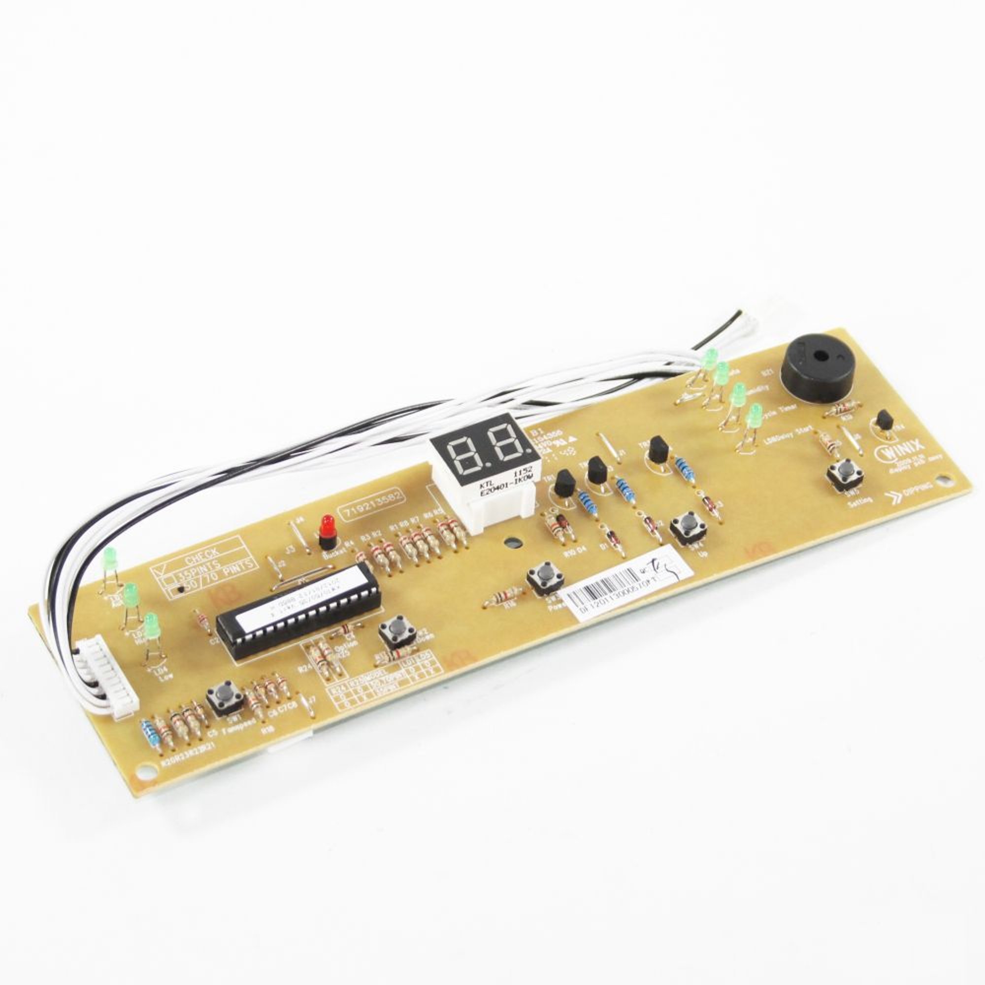
It has two boards, one under the control panel and one inside. The control panel board has the buttons to adjust fan, humidity etc. and the humidity sensor is connected to it. The main board has the relays for turning on the compressor and fan. Also has a transformer for power, and a typical 4 diode rectifier, caps and 5V and 12V voltage regulators. I don't have a schematic but likely the 5V is fed to the control panel board which is working fine, and the 12V feeds the relays on the main board.

Now, the fan comes on as though the machine wants to run, so I figure the humidity sensor is working and the control board is sending signals to the main board to turn on the fan and compressor, but the compressor isn't coming on. Either it's broken, not getting the message, or has a bad start or run cap.

There is a 40 uf cap next to the board that measures 39.8 uf so I think that's OK. This is probably a run cap due to the 40 uf rating (start caps are higher).

I checked for voltage at the compressor, nothing.

There was 120VAC on one side of the compressor relay but not on the other side. This confirms it is not switching.

I briefly jumpered across the relay and the compressor motor began to start up.

Here is where I start to bog down on troubleshooting. This board has, in addition to the two 3-pin voltage regulators and rectifier diodes: 3 small can caps, 3 small transistors each with a diode, two rectangular stacked film caps, one big relay for the compressor and two smaller ones (probably for two fan speeds), a Zener diode and a couple resistors. I'm not sure how the actual control circuit works.

Should I...
1) Try to figure out whether the compressor relay is getting a turn-on signal and if not, why not
2) Replace the compressor relay ($5)
3) Replace the entire board ($35 from Sears)

Any ideas? I feel like I'm tantalizingly close to fixing a $200+ appliance here.
 
Isolate the relay coil feed and power it up from an external source.
Most hvac relays/contactors are 24vac coils but may not be the case here.
Also it may have a low freon pressure switch that is open.

Bob
 
OK. Relay says right on it it is 12VDC and that's confirmed by the part # JQX-102F-P which is sold all over the place.

So I could use a 12VDC power supply like a spare AC adaptor I guess. Good idea. I will try that.

As for the compressor, it has two gadgets on top of it. One has a wire going to it from the compressor relay and another coming out to the other thing mounted on the compressor. It's basically a disk held against the compressor. The wiring diagram labels it OLP. I think this is a temperature controlled overload shutoff - OLP = overload protection?

The second thing is a cylinder sunk into the top of the compressor housing with 3 terminals labeled C, S and R. It almost looks like a cap but it is really glued in there and cannot be removed to verify. Power from the OLP goes to terminal C. The outboard motor run cap is across S and R.

There may indeed be a low freon sensor - there is a short piece of 1/4" copper tubing soldered to the line at the radiator, with a two conductor wire coming out of it to this main board. That may be a pressure sensor?

I'll try firing it up with an outboard 12V supply and if it doesn't cool, I assume that means loss of freon. It's 410A so the question then will be how to figure if the leak is in the compressor, at which point we're sunk I think. But I'm getting ahead of myself.

Thanks for the help!
 
you should be able to ohm out the pressure switch. They're closed when they see enough pressure.
 
That's actually a 'defrost sensor'. Basically the same as a low freon sensor? Don't the coils freeze up when the freon is low?
 
Is the pressure switch you're referring to what is embedded in the compressor? I will check for continuity between those C S and R terminals on it. But since the compressor did fire up when I jumpered the relay contacts, I think there is nothing wrong with this CSR gadget.
 
The 3-terminal "CSR" device shows 0 ohms between all combinations of terminals. If that is a pressure switch it appears closed.

Gotta find a 12VDC supply, looks like it only needs 0.9W to run the JQX relay which is under 100 mA so almost any wall wart should do it.
 
please list the sears number so I can look it up. 123.12345678
 
Last edited:
upload_2017-6-3_20-5-25.png

This it?

J1313100270 board.

What are the markings on TR1, TR2, TR3, IC1 & IC2 ?
 
Last edited:
It looks to me that the J1313100270 board is just the "drive board", and only does what it is told to.
TR1, TR2, TR3 are just logic level signal to relay coil drivers.
The brains of the operation is the other board, the J3150004240 which sends out the signal to close the relay.
The signal probably comes in on CN14 from the brain board.
Voltage measurements or reverse engineering the foil traces to the compressor relay will give us the parameters to determine (fake turn-on the compressor relay) that the drive board is good, and the brains need replacing. OR spot a drive board problem.
Again, the part numbers on the transistors and IC's of the drive board with a picture of the back of the drive board are needed. The drive board would be repairable, the brains board (and the humidity sensor board to be safe) would be replaced.


PD_0042_251_J3150004240
 
Last edited:
Probably one of the boards like mtf says.
Relay coils rarely go bad ,it's usually the contact tips that burn/weld.
Power up the relay with 12vdc and let it run for a half hour or so.
If it makes water and doesn't overheat/crap out then it's worth continuing to invest time and/or money into the circuit boards.

Bob
 
Cool, I'll do some more testing soon as I can get back to it and post the results. I thought that's what those little transistors did. I figured if the fan came on the brain board was good, but now that I think about it, the fan and compressor go on and off a few seconds apart, so they are controlled separately. So it's possible the signal is not coming from the brain at all. One step at a time. I really appreciate the help guys. There is nowhere to get stuff like this fixed anymore for what it costs to buy a new one, but I hate to toss things if they are fixable.
 
Well it took longer than I expected but I did some more diagnosis.

Soldered a couple wires onto 12V compressor relay contacts on the back of the board and hooked them up to a 12V 100ma adapter. I wasn't sure which way should be + and - so I took a guess. Compressor did not start. Immediately switched everything off and swapped polarity on the 12V. Fired up the unit and the compressor started! So the 12V compressor relay is OK, but it does not seem to be getting any voltage.

Now it appears it must not be getting signal from the 'brain' board, OR it is getting lost somewhere on this driver board. I'm going to dig back in with a meter right now, trace the board and see if I can find out which contact the control voltage from the brain board should be coming in on, and where it is dropping out.
 
Last edited:
I can't really make sense of this board. I did figure out that the terminal on the compressor relay that switched the relay when +12V was applied to it, is also connected in common with a terminal on each fan relay, and to the output of the 12V regulator (7812a). Seems to me if that was energized all the time with the regulator's output, the compressor and high fan speed would be ON all the time. Also, the fan relays (at least one anyway) is already working because the fan runs. So there is something I'm missing here. I'm also not sure what to use as a reference for the DC voltages. In over mah head! :confused:
 
not that it matters right now but c s r are as far as i know common start run .
there should be a pressure switch in the pump next to those connectors .i guess that might be good as it runs when you energise the relay . i worked on a chiller cabinet a while back . these things look pretty much the same thing . it turned out the gas had leaked out . so it wouldn't start up . beyond economical repair .
 
Yeah I think we established that the coolant pressure was OK since that switch was closed.

Realized markthefixer asked fora pic of the back of the board and I had not posted. Cannot find a schematic for it. Would be nice if I could annotate what things are but my computer has just been restored and I have no Office software, only a browser at present.

IMG_0251.JPG
 
Back
Top Bottom