Tx-300 amp

Catmanboo

Analog guy, meet digital world - HELP!!
Subscriber
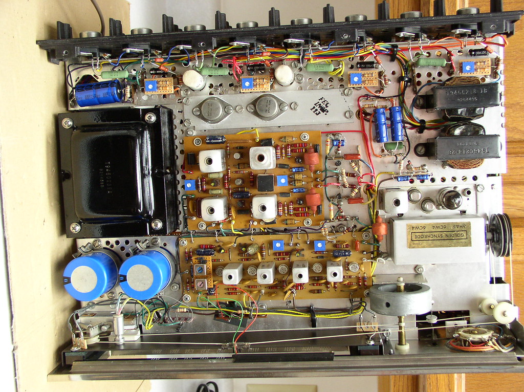
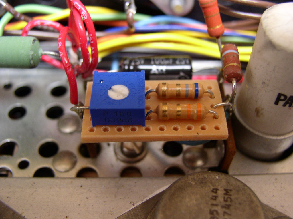
My tx-300, dug out of storage, has a weak channel, I believe to possibly be bad coupling caps. All have swelled, dried-out rubber seals at the positive ends. Knowing about the germanium transistors, the outputs in q1-4 are marked tr35144D,whIle q5-8 are marked tr-35144A. Old logo rca's. Barely readable due to surface corrosion, I suspect this was once in a console. Are these compatible to swap positions for ops check? I suspect they're good, as are the 4 fuses. Any weak points in these? Fwiw, s/n 10091a. Haven't gotten to serious poking/prodding yet due to work & 2 500c's, a 400 & x101d ahead of it.
 
The manual shows the outputs as 35144, and 35524 with 2 of each in each channel. I never advise swapping outputs from one side to the other as this can take out good outputs, or the good driver board. . I would check them all individually to make sure they are indeed all PNP Germanium. And agree with you most likely cause would be an open coupling cap.
 
There is basically no difference between the TR35144 and TR35524. Later units used all TR35144. but, they must be matched for beta within a channel. This was typically indicated with a color dot on the flange, indicating a beta group, or range of beta. Unfortunately, while swapping different beta transistors between channels is ok, the bias would need to be readjusted. That is a major problem on these units because the bias pots are open frame wirewound, likely dirty, and if they lose contact during adjustment, bias goes to maximum and the transistors blow up, followed by the fuses. I restored a 600-T receiver (same power amplifier circuit) and modified the bias adjustment such that it is more reliable. The pots are sealed Bourns style and the series and parallel resistors "trap" the value to approximately half to double the proper bias.

Here is the revised schematic.

p3
12467912185_3c41ff2fa4_b.jpg


Pictures of the bias adjustment modules.

1407
12421427704_56a70725e0_b.jpg


1424
12421163905_a6739a8846_b.jpg
 
Much appreciated info, Fred! I've not touched this thing yet, good to know in advance to not screw with the bias rheostats. Would the outputs be marked on top or underside of flange? I didn't notice any colored marks, but haven't removed one yet to look underneath. Pics to come later.:)
 
Cat. Normally on the top. Paint dot. I've only seen 2 transistors painted such on a 1/2 dozen 49A and 59A amps plus a TX-100 and a TX-300. Good possiblity that the paint either faded or crumbled off. It may have left traces tho. Inspection of the top with a magnifier may turn up traces of color. As these transistors DO get quite warm to hot, the paint probably dried up and flaked off.

Larry
 
Larry, you're right, orange dot on all 8 of 'em, don't know how I missed it.
Wow, pic uploads a lot faster now for some reason. I like!:D
 

Attachments

  • 20180426_201924.jpg
    20180426_201924.jpg
    55.9 KB · Views: 18
  • 20180426_201535.jpg
    20180426_201535.jpg
    84.5 KB · Views: 22
  • 20180426_200952.jpg
    20180426_200952.jpg
    60.1 KB · Views: 16
  • 20180426_200941.jpg
    20180426_200941.jpg
    64.2 KB · Views: 16
Back
Top Bottom