When we bias a tube amp what are we measuring?

Hello Roger. What we are setting is the Q Point on the tube's Load Line. If the Idle Current is too low, then the tube will run closer to cut off than it should, causing the output signal to clip earlier on negative peaks ( I believe). If the Idle Current is too high (what I call overbiased), then the tube will run closer to saturation, causing the positive output peaks to clip earlier.So then yes, the idle current does affect power.
Then, it ultimately comes down to setting the Idle Power Dissipation between longevity and low distortion. I follow the 70% Rule.... I think you know the rest.

I encourage you to try it out. All you need is a load, scope and generator. That is what I am looking at on my bench. In every PP amp that I have tested I can dial the bias up and down and see the obvious change in distortion but the voltage at clipping remains unchanged. I do this to find the sweet spot between distortion and tube idle current.
 
Maybe it would be better to address the power output issue by defining it as "undistorted power output", with the term undistorted defined by the absence of any visible clipping or crossover distortion. :)

Dave

Dave, Thank you for a clear question. According to John Atkinson clipping occurrs at 1% THD. (total harmonic distortion). He relaxes this to 3% for SE amps.
Sometimes amplifiers exceed 1% THD before they clip. Those guys should not send their amplifiers for JA to test. Do they not know the rules?

Amplifiers with reasonable feedback will stay below 1% THD up to clipping. All mine do, so I can send them to JA :). I also make sure the noise is low and the dampling reasonable but that is another concern. You may have noticed the known brands that Never Ever show up on Stereophile. They are the smarter of the over 1% guys who understand the rules. I agree wholeheartedly with John's test procudure and his amp tests are the first thing I turn to when the mag arrives.

Crossover distortion will start a long discussion about cathode biased amplifiers. We can save that for now.

For clipping power the best test is a tone burst because it is most like music. It is the basis of dynamic power specification, which I feel is an additional and valuable test for listening to music as opposed to full level sine waves.
 
"swinging to its full porential" I meant to apply to both A and AB1. In an AB1 amp there is a portion where both tubes are conducting, so changing the bias affects the output swing allowed where both tubes are conducting. I hope that helps clarify.

Oh that is entierly different. What you say now is true but that's not what you said before. Are you doing a Trump do over on me?
 
I've always thought of bias as steady state cathode current, at zero signal. When I measure the bias current, I measure mA, or, I measure volts across a resistor intended to facilitate easy measurement of cathode current but I immediately convert it to mA. If someone asked me a question like what is the correct bias value for a Dynaco ST-70? I would say 50mA for each EL-34.

The reason for thinking current rather than voltage, is that the cathode current is what I set, when I bias an amp. Sure varying the grid voltage is what causes the cathode current to vary, but I never set the grid voltage to say - 34V, the cathode current is the measured variable, so from a workbench perspective setting the bias involves adjusting cathode current to spec. I find it interesting and a bit surprising that there's controversy here, but I do see your point. On the one hand, the phrase bias current seems absolutely correct, and on the other, the C battery in an antique ratio is the bias voltage. Is it possible both can be correct?
 
Biasing matters greatly because it's the center point around which the output signal swings. Get the biasing wrong (too hot or too cold) and the output signal may not be able to swing to its full potential as designed by the manufacturer, or it may cause significantly more distortion than expected by the manufacturer. So it's really important to get the biasing set right so the best performance of the amp can be obtained.

The technically correct definition of a bias point for a triode a set of three values that define the tube's quiescent (zero signal) operating point, and for a pentode, it's a set of four values that define the tube's quiescent operating point.

For a triode, the bias point is defined as:
a) The current at the plate
b) The voltage drop across the tube from plate to cathode
c) The voltage differential between cathode and control grid

For a pentode, the bias point is defined as the above three, plus
d) the voltage differential between the screen grid and the cathode

All three (triode) or four (pentode) must be simultaneously stated to completely specify the "bias point" or "quiescent point" for the tube in question.

For the output stage of a power amp, amp manufactures will sometimes provide a user adjustable mechanism to set the output stage bias by allowing the voltage difference between cathode and control grid to be adjusted within a certain predetermined range, which once set, will automatically set the other values.

The terms "cathode bias" and "fixed bias" are also used routinely to describe the method by which the voltage differential between cathode is control grid is provided. Regardless of which method is used, the above three (triode) or four (pentode) parameters must always be set for the tube to be biased. "Fixed bias" means the voltage is applied to the grid that is more negative than the cathode voltage, and sometimes this voltage is made adjustable, so you might hear the term "adjustable fixed bias." Whereas "cathode bias" means the cathode voltage is made more positive than the control grid voltage by placing a resistor in the cathode circuit that when current flows through it, it creates a voltage potential at the cathode that is more positive than the voltage at the control grid. In both cases, the thing being manipulated is the voltage differential between cathode and control grid.

Re-reading this there are some good points and correct thinking, which is so rare. May I make a few suggestions?

in this: Biasing matters greatly because it's the center point around which the output signal swings. Get the biasing wrong (too hot or too cold) and the output signal may not be able to swing to its full potential as designed by the manufacturer, or it may cause significantly more distortion than expected by the manufacturer.

I think people make too much of bias so I would do the following : take out greatly, it aint that great.
.
Bias is not the center point. The center point is unaffected by bias.

The word "potential" implies a voltage. One might say the amp might not meet spec due to more distortion. BTW distortion is the main thing that changes with idle current in typical amps. Is can affect damping as bias is raised in no feedback triode amplifiers, but that is rather specific and in invite you thoughts on that
.
As far as getting the bias right, there is no right bias. Users are welcome to run the idle current higher which generally reduces distortion and shortens the life of the tubes. Because I want to be known for long tube life and reliability I design for and choose a bias I feel will give good tube life and keep the THD below 1% at clipping. I designed the RM-9 for a tube life of 10,000 hours. ARC is happy with 1,000-2,000 hours. From a design point of view high idle current makes amplifier design very easy as it reduces distortion and makes the feedback stabilization much easier, or no feedback at all which makes it childs play.

in this For the output stage of a power amp, amp manufactures will sometimes provide a user adjustable mechanism to set the output stage bias by allowing the voltage difference between cathode and control grid to be adjusted within a certain predetermined range, which once set, will automatically set the other values.

What amplifiers automatically set the other values? What other values? Do you mean to say: Adjustable bias will bring the other parameters to what the manufacturer intended.

In editing my edit here it came to me again what bothers me. If everywhere you used the trerm idle current rather than bias I would have little to say. It is only the idle current we want to set and monitor. We really don't care what BIAS is required as long as the adjustment pot doesnt run out range, and it does on some amps.
 
Last edited:
Hi, Someone help :( Where is the delete button???? I want to trash something I havent posted and just want to delete.
 
I've always thought of bias as steady state cathode current, at zero signal. When I measure the bias current, I measure mA, or, I measure volts across a resistor intended to facilitate easy measurement of cathode current but I immediately convert it to mA. If someone asked me a question like what is the correct bias value for a Dynaco ST-70? I would say 50mA for each EL-34.

The reason for thinking current rather than voltage, is that the cathode current is what I set, when I bias an amp. Sure varying the grid voltage is what causes the cathode current to vary, but I never set the grid voltage to say - 34V, the cathode current is the measured variable, so from a workbench perspective setting the bias involves adjusting cathode current to spec. I find it interesting and a bit surprising that there's controversy here, but I do see your point. On the one hand, the phrase bias current seems absolutely correct, and on the other, the C battery in an antique ratio is the bias voltage. Is it possible both can be correct?

HI max, You are absolutely correct in your understanding of what is going on. Just don't put the words bias and current together. Bias is a voltage not a current, and idle current is a current not a voltage, though this is what we read.

Do you ever measure the BIAS voltage after you bias the amp?.. One of those nown and verb things :). I'm sure you notice and might like to report to the others here the range you see and the range of the pot. Also have you measured how distortion varies with idle current (note I did not say bias).

In a way we got in trouble when the popular language became "How do bias my amplifier ?" The correct language would be "How do I adjust the idle current on my amplifier?"

When you get right down to it, the tube itself, who made it and how it came out on the bell curve of that run, determines the bias voltage for that tube. I find the BIAS on the EL-34s in my RM-9 can vary from negative 32-42 volts to obtain 30 mA per tube for the four tubes. If I put in KT88/6550s that range is more like 40-50 volts.
 
Ok, so I had to see what Langford-Smith has to say about it. Looks like your frustration is justified.. See attached, it leaves no room for interpretation.

From this day forward I will adjust the bias to set the idle current. I think the confusion comes from just this, when we turn the knob marked "bias" we look at the meter marked "current" and two and two get put together.

DSC_1005-1024x578.JPG
 
Ok, so I had to see what Langford-Smith has to say about it. Looks like your frustration is justified.. See attached, it leaves no room for interpretation.

From this day forward I will adjust the bias to set the idle current. I think the confusion comes from just this, when we turn the knob marked "bias" we look at the meter marked "current" and two and two get put together.

View attachment 1291786

Thanks for hauling out Langford-Smith. I do hope that settles it here at least. I encourage everyone participating on this threat to take up the crusade and spread the word.

My next question is "How did unbalanced become single ended?" Single ended refers to a Class A amplifier that has only one active output device. (ie, its not push pull). Why do audio enthusiasts want to mess up the tried and true terms?
 
I googled "tube bias current", and a lot of hits came up, including this explanation:

"Fixed biasing means the tube is biased by means of a DC voltage, which is usually a negative voltage applied to the grid of the tube with respect to the cathode. As the negative grid voltage is adjusted, the bias current will increase or decrease, depending upon the direction the bias voltage is going. In general, as the bias voltage becomes more negative, the bias current becomes smaller, and the tube is biased "colder". As the bias voltage is adjusted less negative, towards zero volts DC, the bias current becomes larger, and the tube is biased "hotter". This is because a tube is a "normally on" device; that is, it allows current to flow from the cathode to the plate when the grid is at zero volts with respect to the cathode. The tube can be turned off, and the current flow stopped, by making the grid voltage negative with respect to the cathode. The tube can also be biased by referencing the grid to ground, or zero volts DC, and applying a positive DC voltage to the cathode. This is the same as keeping the cathode at ground and applying a negative DC voltage to the grid, because it is the grid voltage with respect to the cathode that determines the amount of bias current in the tube."
Ref:http://www.aikenamps.com/index.php/what-is-biasing#

This one is more to the point:
"
What is Bias?
Bias voltage is the voltage difference between a tube's cathode and control grid. Bias current is the amount of electrons flowing from the cathode to the plate with no audio signal on the control grid (idle current).
"
Ref:https://robrobinette.com/How_to_Bias_a_Tube_Amp.htm

And that's just the first couple hits. I believe so long as people turn to the internet as their first stop for information, that the term bias will continue to have a colloquial meaning different from what it originally meant.

My first stops for clarity on old tube concepts are always Langford Smith, and the Audio Cyclopedia.. But how many people have those books anymore? English evolves, and the colloquial definition will eventually become the accepted one. If I were in your shoes, I would probably write the amp manual to avoid the term bias entirely, e.g. "connect the red lead of the meter to test point one, the black one to the ground terminal. set the scale to volts.., adjust VR1 until the voltage is between X and Y"
 
Last edited:
I googled "tube bias current", and a lot of hits came up, including this explanation:

"Fixed biasing means the tube is biased by means of a DC voltage, which is usually a negative voltage applied to the grid of the tube with respect to the cathode. As the negative grid voltage is adjusted, the bias current will increase or decrease, depending upon the direction the bias voltage is going. In general, as the bias voltage becomes more negative, the bias current becomes smaller, and the tube is biased "colder". As the bias voltage is adjusted less negative, towards zero volts DC, the bias current becomes larger, and the tube is biased "hotter". This is because a tube is a "normally on" device; that is, it allows current to flow from the cathode to the plate when the grid is at zero volts with respect to the cathode. The tube can be turned off, and the current flow stopped, by making the grid voltage negative with respect to the cathode. The tube can also be biased by referencing the grid to ground, or zero volts DC, and applying a positive DC voltage to the cathode. This is the same as keeping the cathode at ground and applying a negative DC voltage to the grid, because it is the grid voltage with respect to the cathode that determines the amount of bias current in the tube."
Ref:http://www.aikenamps.com/index.php/what-is-biasing#

This one is more to the point:
"
What is Bias?
Bias voltage is the voltage difference between a tube's cathode and control grid. Bias current is the amount of electrons flowing from the cathode to the plate with no audio signal on the control grid (idle current).
"
Ref:https://robrobinette.com/How_to_Bias_a_Tube_Amp.htm

And that's just the first couple hits. I believe so long as people turn to the internet as their first stop for information, that the term bias will continue to have a colloquial meaning different from what it originally meant.

My first stops for clarity on old tube concepts are always Langford Smith, and the Audio Cyclopedia.. But how many people have those books anymore? English evolves, and the colloquial definition will eventually become the accepted one. If I were in your shoes, I would probably write the amp manual to avoid the term bias entirely, e.g. "connect the red lead of the meter to test point one, the black one to the ground terminal. set the scale to volts.., adjust VR1 until the voltage is between X and Y"

Hey Max, thanks for joining the crusade. I can barely count the number of times the guy uses the word BIAS. He has no problem using it for both votage and current. Its his favorite word :) He likes it as a verb also.

I commend the second guy for at least putting (idle current) at the end of the sentence.

When I see the words bias and current next to each other I cringe.
 
My next question is "How did unbalanced become single ended?" Single ended refers to a Class A amplifier that has only one active output device. (ie, its not push pull). Why do audio enthusiasts want to mess up the tried and true terms?

I seem to remember first reading single ended in that context, as a perjurative term used by people marketing balanced connections for home use. Balanced connections make a whole lot of sense in a professional environment, but are much hard to justify in a domestic system. So why not use a perjurative term against the alternative, rather than come up with an actual valid reason? Why settle for single ended, when you can have balanced? Now we are just stuck with marketing language used in place of the original technical term.

Maybe I am wrong about how that developed, that's my theory though.
 
There seems to be some confusion about biasing a tube amplifer. I would like to ask the readers here to give their thought on what are we adjusting and what are we measuring when we adjust a tube amplifer's bias.
On my cathode biased amps I adjust the cathode resistance, and I measure the parameters that tell me the valve dissipation power, and set that at a certain % of generic datasheet rated dissipation (assuming its a vintage valve). On my fixed bias amps I adjust a potentiometer, and I .....

For me, I don't have to assess the 'bias' to perform 'biasing'.

And for me, biasing of push-pull amps includes more than dissipation setting, it also includes current balancing.
 
Roger, most of your edits to my original text don't change my intended meaning, so I don't have a lot to say about them. A few clarifications:

As far as getting the bias right, there is no right bias.
My point being from the perspective of what the manufacturer recommended.

What amplifiers automatically set the other values? What other values? Do you mean to say: Adjustable bias will bring the other parameters to what the manufacturer intended.
I was thinking unregulated power supply in an AB topology. E.g, changing bias point to draw more idle current in an AB1 output stage will slightly droop plate voltage. Setting idle current to manufacturer recommendation will certainly bring the "other parameters" to manufacturer intended values.

It is only the idle current we want to set and monitor.
I also want to know plate voltage, cathode voltage, plate dissipation, screen voltage, screen current draw, and screen dissipation. I don't monitor any of these values continuously, but I want to be aware of their values during the process of deciding what bias point I want.

Oh that is entierly different. What you say now is true but that's not what you said before.
In any case what I had in mind when I wrote the original statement from whence this comment sprang was that the bias point of an AB1 output stage does affect things that can be measured. The two I had in mind when I wrote it are distortion and amount of power achieved while both tubes are conducting. In an AB1 amp, setting idle current to one value or another does not affect max output power the amp is capable of delivering.
 
Last edited:
I wrote this many moons ago, it was originally in response to a young lad asking me what Bias was, he told me that they did not teach it in college and he was interested to know.

Why do we need to have this thing called bias?

Suppose you are holding one end of a rope which is coiled on the floor which you want to use to send a message to a partner holding the other end. Obviously, any movement you make to your end of the rope will not be felt at the other end so it will be impossible to send a message. OK, so we take out the coil and have the rope hanging loose between you and your partner. Your partner would only receive something of a message if you jerked the rope really hard with big swings of your arm, the message would be rather distorted and we don’t want that. But if we arranged for the slack to be taken up and a slight steady pull applied (bias?), then your partner would be able to perceive the slightest of movement of the rope so any rope message will now be read without distortion. Too much steady pull (bias) will do nothing more than make both of you feel hot and tired, even when no message was being received, very wasteful. So there is your bias in a nutshell, just enough to keep everything in control and allow the valve to respond to its input signal with the least distortion.

It really is not a black art setting the bias but what is it actually doing? Well there is plenty of info on the internet but simply stated it is like you controlling the water from a tap. By adjusting the little controls, called potentiometers, you are setting the tap to deliver a certain flow of water. Turn it too far one way and you turn it off, not much good! Too much and you get a flood, which in the case of a valve will cause it to get very hot and fail, possibly burning out something else like the very expensive output transformer which feeds it. In our water analogy we would use a flow meter to set the correct rate of water from the tap. In our valve amplifier, the valve currents are made to produce voltages across resistors in their cathode circuits. Thus we can easily measure with a Multi-meter set to measure DC Volts, a representation of the actual flow and in this way we do not have to cut wires to measure the actual current.
An example would be a 10 Ohm resistor in the cathode and the required current to be 0.035 Amps (35 milliamps), the 10 Ohm is chosen for easier calculation as follows:-
We find the required voltage on the 10 Ohm resistor by simply multiplying the required current by 10, i.e. .035 x 10 = .35V.
Thus the flow will be correct when the voltage is 0.35V as shown on the multi-meter.

A very simplistic description but may be helpful to some.

Keep lighting up those filaments - Les
 
I have another comment about this topic:

Tube amplifiers are for all intents and purposes an obsolete technology. No academic institution has covered them in any sort of detail for generations, and only the oldest members of this forum will have had any sort of formal training. When I was studying electrical engineering in the 1990s and early 2000s, even discrete transistor amplifiers were not studied in great detail. The focus was digital, FPGA's, microcontrollers, and so far as analog goes, op-amps. I remember one lab where we had to build a three stage discrete transistor amplifier, and I threw off the instructor by making it direct coupled, eliminating the output transformer, and adding decoupling capacitors. No thanks to anything I learned at university, though! I built my first tube amplifier when I was a young teenager, and since then 100% of what I know about tube amps has been due to personal interest and self study.

Given the absolute vacuum of formal education on the subject (no pun intended!), and the scattered and sometimes questionable resources available for those wanting to learn, it's no big surprise that terminology has lost or changed meaning. Frankly it's amazing that at this stage in the game there's even anyone making tubes anymore.
 
In an effort to simplify things a bit, there IS a hard limit to how high you can set your bias. Increasing the bias setting decreases your B+, and that HAS to stay above the lower threshold of the design spec.

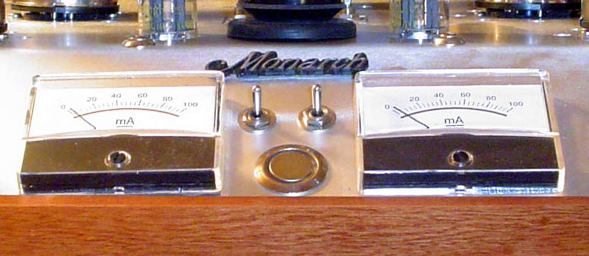
And of course, in an effort to complicate things again, here's a pic of my bias meters on the latest build ... MA you say? ;-}

bias-meters-ma.jpg

Well, your meters are indicating the quiescent current that results from the bias setting. Really I don't understand the degree of fuss over the semantics here, as long as it's understood that the quiescent current is set by the bias conditions, I'm not sure of the crime in considering the quiescent operating point related to the bias or in terms of the bias. For those writing text books on the topic, yes it would make sense to be literally precise, for comments on a forum I don't see the need for the semantic argument.
 
Back
Top Bottom