When we bias a tube amp what are we measuring?

I have another comment about this topic:

Tube amplifiers are for all intents and purposes an obsolete technology. No academic institution has covered them in any sort of detail for generations, and only the oldest members of this forum will have had any sort of formal training. When I was studying electrical engineering in the 1990s and early 2000s, even discrete transistor amplifiers were not studied in great detail. The focus was digital, FPGA's, microcontrollers, and so far as analog goes, op-amps. I remember one lab where we had to build a three stage discrete transistor amplifier, and I threw off the instructor by making it direct coupled, eliminating the output transformer, and adding decoupling capacitors. No thanks to anything I learned at university, though! I built my first tube amplifier when I was a young teenager, and since then 100% of what I know about tube amps has been due to personal interest and self study.

Given the absolute vacuum of formal education on the subject (no pun intended!), and the scattered and sometimes questionable resources available for those wanting to learn, it's no big surprise that terminology has lost or changed meaning. Frankly it's amazing that at this stage in the game there's even anyone making tubes anymore.
Here you go...
http://www.audioxpress.com/article/...er-techniques-with-electron-tubes-2nd-edition

plus, of course,
www.tubebooks.org
 
Perhaps the bias on your pic is too high as we're not seeing anything. Something is amiss at "brainfartz.com". ;)

New pic - maybe it hasn't caught up with your end of the world yet ...

Well, your meters are indicating the quiescent current that results from the bias setting.

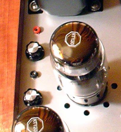
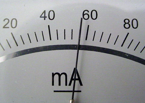
My bad - Was actually being my usual facetious self here. The mA meters are measuring mV - I've fine tuned the circuit to where it's easy to match points for the recommended 55mV per tube and the 60mV I usually run the KT120's at.

big-bottles-bias.jpg


velleman-meter-cu.jpg


(And ya, I know, the scale is off, but it makes for an easy visual. I use a VOM to match the meters to the bias test points using a VR. Long as I know what's happening, I'm good with it.)

I double check occasionally with the VOM, and on the fly settings using just the meters are surprisingly close. I also take them completely out of circuit during normal operation using a center off switch.

Why use mA meters? Because I like the old school look on these, and it was an easy mod - just a simple snip on an internal shunt resistor is all. ;-}
 
Last edited:
It will affect it "greatly." Set it to 100% of plate dissipation and you will have to restrict the input signal level so it doesn't go higher than the bias voltage, if you don't want grid current
No disagreement that changing bias point of the output stage affects the drive requirements of the output stage. My previous statement (not very well worded) was that in an AB1 power amp with a regulated power supply, bias point really has no bearing on maximum undistorted output power the output stage is capable of delivering, assuming the the power amp's input and driver stages can accommodate it.
 
Clearly, if you overdrive the stage it will clip and distort, but I think I am describing something different here.

For an AB1 stage, what defines max undistorted power the output stage is capable of delivering, assuming the frontend stages can provide enough clean drive to accompdate it? I submit it is only the plate voltage (actually voltage across the tube from plate to cathode) and the primary impedance of the output transformer. The OPT primary impedance in turn, along with the tube type, define the current swing possible. So under max undistorted power output conditions, max voltage swing is defined by the stoutness of the power supply, and max current swing is defined by the OPT primary impedance. (And certainly there is a given drive voltage that causes the stage to be put into those conditions.) Power output then is the product of max current swing and max voltage swing. Quiescent bias point then isn't part of determining max voltage and current swings, and therefore isn't part of determining max output power capable in an AB stage.
 
Last edited:
6DZ7, are we talking about the same thing? if you are describing a class A stage then there is no issue.

If you are describing an AB1 stage then I offer just one more point. In an AB1 stage there are two tubes with outputs combined through the OPT. At max power output, while one is conducting, the other is in cutoff. Then 180 degrees later on the input waveform, the tubes swap roles..The output signal isn't prematurely clipped because the output signal is a summation of both tubes' output using the output transformer to do the summation.

I am describing this in the best way I am capable of. If you still disagree, let's just agree to disagree and move on.
 
Okay i see where you are coming from now.

The issue of max undistorted output power capable from an AB1 stage as it relates to bias point setting has never been at issue for me throughout this entire thread. I took some objection early on when another poster assumed I believed max output power was defined by or influenced by bias point setting when I firmly believe it is not.

That is totally different from another point I was making that output power delivered in an AB1 stage while both tubes are conducting has very much to do with bias point setting.

Okay, I'm ready to move on as we both have made our respective points now.
 
Last edited:
I've reread this thread a few times, as well as visiting the Stereophile review of the Music Reference RM9 amplifier! Thanks for those who have taken part as I think it is helpful to get the language straight: bias voltage is measured as a voltage, and the resultant quiescent/idle current is measured as a current. Roger's original questions are answered for me in posts #2, #5, #28 and #31.
 
My next question is "How did unbalanced become single ended?" Single ended refers to a Class A amplifier that has only one active output device. (ie, its not push pull). Why do audio enthusiasts want to mess up the tried and true terms?

Because an unbalanced input has a single signal line. :D That is like asking why people call any adjustable wrench a present wrench.

Single ended refers to far more than just a Class A Amp. OP amps are both single ended input and differential, as well as data acquisition systems.
 
Just leave the entry and clear your browser cache. If you haven't posted, the draft will disappear.

Who would have thought you had to clear you cache... Other forums I use have a delete button. Thanks for hte help E stat.

BTW ESLs rule :)
New pic - maybe it hasn't caught up with your end of the world yet ...


My bad - Was actually being my usual facetious self here. The mA meters are measuring mV - I've fine tuned the circuit to where it's easy to match points for the recommended 55mV per tube and the 60mV I usually run the KT120's at.

big-bottles-bias.jpg


velleman-meter-cu.jpg


(And ya, I know, the scale is off, but it makes for an easy visual. I use a VOM to match the meters to the bias test points using a VR. Long as I know what's happening, I'm good with it.)

I double check occasionally with the VOM, and on the fly settings using just the meters are surprisingly close. I also take them completely out of circuit during normal operation using a center off switch.

Why use mA meters? Because I like the old school look on these, and it was an easy mod - just a simple snip on an internal shunt resistor is all. ;-}

I like your meters but I am confused. If the meters are already made as current meters with at proper shunt why snip it out? What replaces the shunt?
 
I seem to remember first reading single ended in that context, as a perjurative term used by people marketing balanced connections for home use. Balanced connections make a whole lot of sense in a professional environment, but are much hard to justify in a domestic system. So why not use a perjurative term against the alternative, rather than come up with an actual valid reason? Why settle for single ended, when you can have balanced? Now we are just stuck with marketing language used in place of the original technical term.

Maybe I am wrong about how that developed, that's my theory though.

Thanks max. As good an explanation as any. Once again marketing rules and messes things up. I went to the trouble of making the RM-200 have excellent CMRR and at the same time identical performance running it unbalanced. I guess I need not bother as "single ended" has returned and our efforts to solve a big problem for the mono amp people has been ignored. It is virtually impossible to have two mono amps, both grounded via power cord to not hum. With "single ended" one amp has to float and sometimes the pre-amp too. I note people do not like defeating the ground pin, though traditional amps have not a grounded power cord.
 
It will affect it "greatly." Set it to 100% of plate dissipation and you will have to restrict the input signal level so it doesn't go higher than the bias voltage, if you don't want grid current. Set it to 2mA and you have a class AB (almost but not B) amp you need a huge drive signal to get to grid current but you are only going to get to use half of the signal. That's 2 different power levels the amp is is going to be restricted to.

Set an SE amp to 100% of plate dissipation and you're good. Set it to 0mA and you still get power and half of the signal but it sounds like crap. The bias voltage sets the cuttoff and clipping points @ a given plate/screen voltage. It sets the limitation of usable drive signal.

Your prior posts are spot on, don't let some of stuff misdirect.

The concept of biasing an amp is not a 2 ball juggle, it's more like a 5-6 ball juggle.

There are very few amps and none I can site the "restrict the input signal" or drive to the tube. That would be a bad thing to do because a low transconductance tube needs more "drive" than a high one. In my RM-9 I need 35 volts of drive for EL34's and 50 volts for KT88s. In most amps we have enough drive to get to grid current, then the compling caps charge and things shift but we are not supposed to be clipping amp are we.

When I designed the RM-9 I also wrote a paper about this problem. The much loved Citation 2 has horrible recovery time, seconds of fopping around after hard clipping. I didn't want my amp to do that and took care of it.

You are correct about the SE amp, but lets not encourage people to run them at 100% rated dissipation unless they like burning up expensive tubes.

In a way its a little more than a 2 ball juggle though the other balls tend to fall in place on their own.
 
Thanks max. As good an explanation as any. Once again marketing rules and messes things up. I went to the trouble of making the RM-200 have excellent CMRR and at the same time identical performance running it unbalanced. I guess I need not bother as "single ended" has returned and our efforts to solve a big problem for the mono amp people has been ignored. It is virtually impossible to have two mono amps, both grounded via power cord to not hum. With "single ended" one amp has to float and sometimes the pre-amp too. I note people do not like defeating the ground pin, though traditional amps have not a grounded power cord.

I never thought about that situation. I never use three wire power cords on DIY efforts for exactly that reason, and have never owned mono amps new enough to use them either. Makes sense though.
 
Because an unbalanced input has a single signal line. :D That is like asking why people call any adjustable wrench a present wrench.

Single ended refers to far more than just a Class A Amp. OP amps are both single ended input and differential, as well as data acquisition systems.

I like your Sinatra quote, made me smile.

What is a present wrench. did you mean preset? If so I would hand them a non adjustable wrench. :)

I dont know of any single ended op amps, by definition op amps are differential otherwise they could not perform their "operations".
 
In an effort to simplify things a bit, there IS a hard limit to how high you can set your bias. Increasing the bias setting decreases your B+, and that HAS to stay above the lower threshold of the design spec.

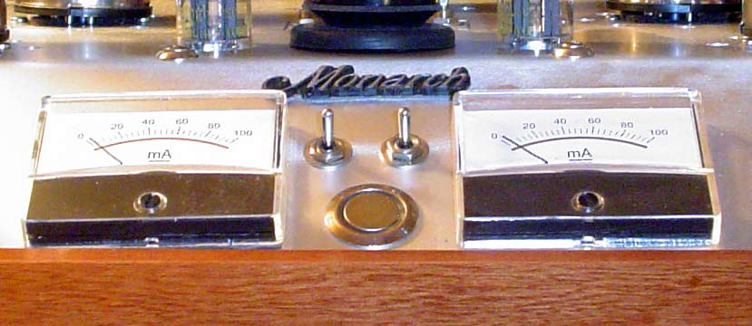
And of course, in an effort to complicate things again, here's a pic of my bias meters on the latest build ... MA you say? ;-}

bias-meters-ma.jpg

I see your switches now and switching them out for their safety is a good idea. . They also provide a way to see when you leave class A. Nice touch.
Also nice they say mA on them since that is what you are reading, the shunt is just elsewhere now. If it turned out that your original measuring resistor was the same as the shunt you were very lucky. Most current meters are set for full scale at 50 mV as that is a common shunt.

As to the decrease in B+ by raising the idle current that effect is far smaller than the droop due to high power levels where the amp continues to work fine.

People should know that in all ampifiers we design for nominal values and a good design allows for variations in those nominal voltages.
 
I gave a talk yesterday at Burning Amp 2018. We had a audience of over 100 in the FIre House. Jim Tiemann, speaking for DIY audio made a passionate plea for those who can to help the new people learn about audio, proper thinking, and building their own stuff.

This talk will be up in about 10 days on the Linear Systems web side. They are sponsors of Burning Amp and makers of the lowest noise FETs current available in new production.
 
Hello Roger. What we are setting is the Q Point on the tube's Load Line. If the Idle Current is too low, then the tube will run closer to cut off than it should, causing the output signal to clip earlier on negative peaks ( I believe). If the Idle Current is too high (what I call overbiased), then the tube will run closer to saturation, causing the positive output peaks to clip earlier.So then yes, the idle current does affect power.
Then, it ultimately comes down to setting the Idle Power Dissipation between longevity and low distortion. I follow the 70% Rule.... I think you know the rest.

Hi triode.

What you say in the first part is true if the driver is wimpy, like in the Stereo 70. The 7199 driver tube in that amp does not bias up uniformly from tube to tube. If you have more than about 105 volts on the cathode you will run out of drive and what you say will indeed happen. For those still using the original 7199 driver a trim pot to adjust the cathode voltage of the split load phase inverter is a great mod. Then you can adjust the cathode to a sweet spot the does affect output clipping.

If the tube is running high idle current there will be no problem as now the driver has to provide less drive.

Keep in mind the Q point on the load line does not affect the load line.
 
If there isn't sufficient bias voltage to keep it from clipping then the output swing is clipped. Power clipped.
.

Bias voltage has nothing to do with output swing as I have said before. Driver output determines swing. As long as the grid gets to zero volts in a AB1 amplifier that is full power. Mosty amplifiers achieve this with no problem.

Please support your statement.
 
Last edited:
The one concept that is getting missed is the final bias voltage level at the grid. It sets the limit of the usable signal.

Situation: The book says set the idle current to 50mA and that is = to 1v on the test point. So you do and you think everything is just great. But what you don't realize is the tube is defective, worn out, misbehaving and to get your perfect 1v test volt across your 1% super precise cathode test resistor you turn the bias pot without knowing what the grid voltage is but one day you check and you see it's -10v instead of -35v. WOW, how could that be so different from what the manual says it's supposed to be? The amp sounds great all day long! It's because you never turn the volume control up past 2 and never send a drive signal higher than 10v peak. Drive it to 20v and see what you think about power and distortion. Just setting the idle current is only part of the story.

You could have 4 tubes dead on 50mA idle current but with grid voltages 5v apart. Being driven to ....full power?

Very good point and why we want matched tubes. Even with unmatched tubes and individual bias pots if the bias voltages are set quite differently as you describe there will be a problem of sharing current at full power

Now this is a great reason for making the distinction between bias and idle current. If we don't have those two terms we cannot describe this problem as 6DZ7 has so clearly put. THANKS:).
 
Back
Top Bottom