X202B: new 1000uf/1000uf can blew up

rufleruf

Poor Impulse Control
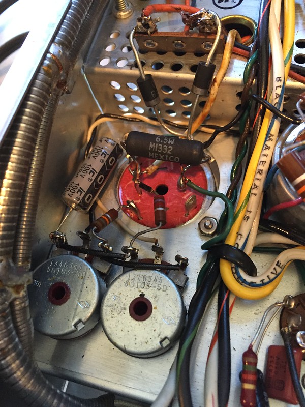
I bought a 2x 1000uf x 50V can cap from a well known seller to install in my working X202B - caps C53A & B. Installed it last night, also replacing the 2 diodes (SR3 & SR4) that go to the can (+ side) and R121 a 15 ohm, 7W resistor that bridges the negative side of the two 1000uf's. Replacement is a 6.5W item.

It passed DBT, so I powered it up on my variac. After about 2 minutes and at maybe 70% on the variac the can cap popped and shot some smoke out.

I'm suppose there are three possible failure modes: the can was defective in some way, it saw more than 50V, or it saw more amperage than expected.

I had maybe an hour of listening on this unit since a recap, I just thought replacing this cap would be a good idea.

Anyone care to guide me in some testing before I attempt a repair? From pin 4 of one of the 12AX7's to the junction of the diodes and the common + of C53 I get about 7.5VDC at 70% - seems reasonable. I guess it's probably a matter of current - maybe I need a current meter.

 
First, confirm that the new can cap was built as a CAN POSITIVE can. That is, instead of the can body itself being the traditional negative terminal of the internal caps, in this case, the can body should be the POSITIVE terminals of the internal caps. If this is not the case, then the caps were effectively wired in backwards, giving rise to the magic smoke.

I hope this helps!

Dave
 
I don't know what cap is for off top of my head. But, some caps like those part of a bias circuit are installed "backward" meaning (+) to ground/chassis since the bias is negative with respect to ground.

I suggest confirming polarity of the circuit as first step.
 
Guys, thanks for the quick replies - I only have a little while this morning to work.

The can is COM - POS per the label, so it's wired correctly - the 100uf 100w replacement for the 50uf 70w electrolytic is the right way around as well. Pretty sure the diodes are in right too.
 
Maybe whoever built the thing wasn't paying attention to the label ... it happens.

I suppose one easy test to narrow things down would be to try two separate caps - if those still blow, you've got problems elsewhere ...

Wondering about replacing that 50uf with 100uf? Common practice to increase the voltage rating, but you're way out of range on the circuit doubling the uf rating. Common mod, or just what you had?
 
I just tested the can in circuit with my IT28 cap checker - one side seems fine -the tuning eye opening nice and wide right around 1000uf (unfortunately the last value at the end of the extended scale - which appears to be a log scale, so a tiny variance could be 100uf) , the other side not so much - tuning eye barely opens at the same setting. Maybe I should test it with polarity reversed. Haven't figured out how to do leakage with cans - maybe it's a matter of patience. Might want to read the manual again.

I am going to graft a 1000uf x 50v radial I have laying around in place of the second one and see how it does.

I bought two of these cans, is there a way to verify the polarity of the other before I hook it up?

100uf is just what I had on hand in an axial. I think I have a 47uf x 100v I could put in there if it matters.
 
Last edited:
Okay, so I put a 1000uf x 50v I had laying around in place of the side that didn't test well and swapped a 47uf x 100v for the 100uf x 100V I had going to the common positive side.

Powered it up and after a couple minutes the other side of the can cap blew. Swapped in another 1000uf x 50v and now it works fine.

Either they packed the can with too low voltage sections, got the polarities wrong, or the 100uf cap being double the capacitance was indeed a problem. Time to cut and stuff a can and make it all right.

On the bright side - it sounds really good!
 
Installing a 100 uF cap where the 47 uF originally was had nothing to do with this problem, and was a perfectly acceptable replacement, and even represented a nice upgrade. Since it appears after the 2.7K resistor, even if that cap was a dead short, it would only pull 9 ma from the supply, and not even over-wattage the 2.7K resistor, either. This was a problem that existed entirely within the can. Most likely, it was never built as a common positive can, or improperly labeled as being such if that is what it is labeled to be. Sounds like you are either owed a proper can for the application (with free shipping) , or your money back including shipping costs for the bad one.

Dave
 
Dave,

Thanks for the vote of confidence. The MFR of the can is well regarded and I'm sure will be happy to have the defective unit back to see what happened, and will either send me another one or make a refund. The hard part is I bought two, and I'm looking at the other one, thinking swapping it in is the easiest course of action right now, and then I think about the hour I already lost...
 
Ruf -- It's easy enough to see if the polarity of the other can is correct as labeled, using your amplifier (with the replacement discrete caps still installed) as the test bed:

With your new can, connect one of its can common terminals to the point in the circuit where it would normally connect to were it installed (the output of the rectifiers). Use alligator clips to make the connections. Now connected to two cap (supposedly) negative terminals to the points where they would normally connect to as well, but each through a 10K .5 watt resistor. Now turn the amplifier on. If the can cap is of the correct polarity, the voltages across each section will mimic those across the relevant discrete cap sections they are connected across. If the can cap is of the wrong polarity, then the voltage across each section of the can cap will be very low, but the resistors will prevent any damage to the amplifier, or the can cap itself, which could then be relabeled and used in an appropriate application that it is polarity correct for, or, returned to the manufacturer as unused and in undamaged condition for credit and proper labeling. If the polarity is in fact wrong, the resistors would limit the improper (reverse) current flow through the caps to about 2.5 ma each, which is entirely insignificant.

I hope this helps!

Dave
 
Alright - by your test the other can is correct. I guess I'm going to dive in and swap out the can.

An aside - how hot would / should the 15 ohm resistor between the two negative terminals get? Was surprised how warm it was when I bumped it checking voltages.
 
That resistor is dissipating as much as 5.4 watts in normal operation, so it will normally get quite hot. As a result, it is best to position it so that the can cap is not directly under it (or over it when in operating position -- heat rises), and it is near the fresh air vent holes as well.

Dave
 
Another one bites the dust. Got to just over 50% on my variac when the first side popped. All that makes sense at this point is they grabbed 16V or 25V instead of 50V when they made them. Another argument for stuffing your own caps. If you screw it up it's on you.

Hopefully they can take them apart and do some QC, because I'm certainly not buying from them again.
 
What did those cost ya? I'd be tempted to tear one down myself and see what's inside ...
 
They were just under $30 each. The X202B is the nicest piece I have so I thought I would splurge - I usually just restuff the 2x 1000uf cans in the receivers with some Panasonic 1000uf x 50V radials I got bulk on the bay.

I'll send them back tomorrow and see what the say.

Two steps forward, two steps back this weekend
 
Interesting. So in the suggested test you performed, you indicated that the can cap passed. That means that you measured about 31 and 22 volts DIRECTLY ACROSS the can in the test, because those are the potentials each section of the can typically operates at when installed. If these are the approximate potentials you measured, then the polarity of both sections of the can cap must be correct, or those voltage levels never would have been developed across the can cap: It would have all been dropped across the resistors.

That leaves the possibility of under-voltage rated caps being installed within the can. Conventional electrolytic caps will withstand an over-voltage surge for a short period of time. Most manufacturers permit a brief 10% over-voltage condition to allow for voltage surges at turn on. How long did you conduct the test? If it was only for a matter of a few seconds, then it is possible that if under-voltage caps are installed, they simply withstood the over-voltage condition for the short time period of the test. If there are under-voltage rated caps installed, then conducting the test for a longer period of time (say 5 minutes or so) would likely have uncovered this fault as well, as they would have broken down due to the severe over-voltage condition that existed during that period of time.

Dave
 
Dave,

I didn't bring it up that high on the variac for the test mostly because I was poking around a really crowded area with test leads (all my alligator clips already being assigned to resistor duty) - I don't remember the setting, but it was such that I measured about 7 volts on one of the sides, and the can cap sides mimicked the caps installed in the unit. I thought the point of the test was whether both sets of caps reacted to the circuit the same way.

I tested the old can I pulled out of the unit last night out of curiosity and got 1000uf on both sides and it passed a leakage test. Might just put it back. The ingredient I was missing on the leakage test was patience - it takes about a minute for the tuning eye to start opening for bigger caps.
 
Last edited:
Epilogue: Just heard back from the manufacturer of the cans. They tested one off the shelf and discovered they were negative com but mislabeled as positive com. They are rushing me out replacements.

I guess the two hours I spent weren't a total waste - I'm much more comfortable pulling and replacing cans that I thought I would ever be.

There's a very old saying. It goes:

"Rutroh!"
 
Ruf -- For the test to be most telling, you would have needed to have operated the amplifier at full AC power (this to absolutely confirm the reverse polarity possibility), and for a period of a couple of minutes, to confirm if any under-voltage rated caps were installed. In any event, you found out what you needed to know from the manufacturer, so no doubt, you'll have it squared away in no time!

Dave
 
Back
Top Bottom