Yamaha A-960 troubles

Nashou66

AK Subscriber
Subscriber
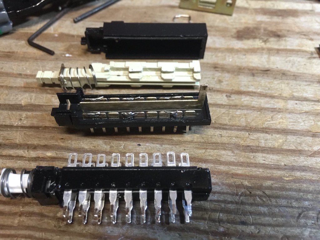
I bought a Yamaha A-960 with a couple issues , First is the Main Direct switch. It looks like someone took it apart and soldered the pins together inside and removed the copper "sliders" that make or break the direct connection so it was set to only the tone control setting. So I bought a 6PDT C&K switch. This one here http://www.mouser.com/ProductDetail/CK-Components/F6UEE/?qs=sGAEpiMZZMvxtGF7dlGNpkvuTQHbvtlSnge8p3X2G5o=


http://www.mouser.com/ds/2/60/Fpush_1nov12-221205.pdf

One difference was the old switch had a center pin at the end of the pins and it was connected to one side of the outer pins on the PCB. The other outer pin on the old switch was not connected on the PCB ( no solder pad from factory)

26907317000_58b4f9a54c_b.jpg

27181927505_07a4817f72_b.jpg

27148801656_7fb9947c5a_b.jpg


Now when I selected the Main Direct switch to by pass the tone control the main power light dimmed and the protection relay clicked on I shut it down right away and now removed the new switch.

So my question is, is the new switch wrong type? I can not tell how toehold switch was exactly inside due to it being bastardized . One thing I did was test how the Disc button opperated as in theory it works the same. and the new switch contacts made the same continuity as the Disc switch( 4 pole vs 6 pole) .

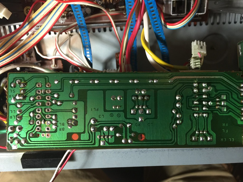
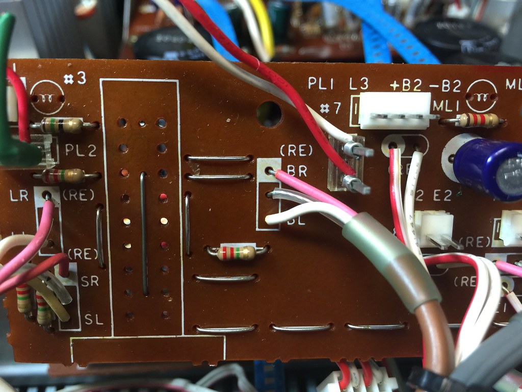
the schematics are not clear as they do not really go into detail on the switch or its internal operation. and the board layout drawing is not the best So that is why I added the pic of the board.

Yammy experts what is my next move?

Athanasios
 
Ok Just found this older thread( forgot to look first doh!!!!) Looks like mine doesn't have the device bulletin done.

http://audiokarma.org/forums/index.php?threads/yamaha-a-960-question.149520/

I'll try that out with the new switch and see what happens . I'll have to get the Zeners tomorrow. And some bulbs . those might not be local so will this service buliten work with out the bulbs?
I also noticed on PL2 some one cute the one wire and soldered the red wire going to the power light . And it looks like all bulbs were re routed possibly? not sure.

27113476431_e81fc69805_b.jpg


Nashou
 
Hi Just got he Zener diodes I need for the Main Direct switch fix( if my new switch is the correct type) . Now on the SB linked in the other thread two diodes are oriented with the Cathode towards the pin's it is suppose to be soldered to while the other one is facing away from the pin and to the resistor. Just want to make sure this is correct and not all three facing the same way.


Service bulletin 05-84.BMP

Athanasios
 
Ok The SB was correct. I used a 12 volt 60ma Lamp from RS. They are smaller in diameter but work fine as I have used them in the A-1's I have here ( 3 now ;) ) so now all three lights work, and amp stayed on !!!

But.....I discovered the Disc switch also is bad. It won't latch. I will open it up tomorrow and check if I can repair it, I have done a couple before. Might just be something not allowing the switch to move all the way back to let the latch catch hold.
After I fix the Switch I will adjust Voltages and then test with speakers. I did a quick cold DC check on the speaker outs and it was high up to 380mv's and when I press the main direct it goes down to 100mv. So these need adjusting.
I'll look it over in the SM tonight.

Thanks for the beer chug Mike, I grabbed a Labatt Blue and am enjoying it as I type.

Nashou
 
Ok the Switch was bad so I ordered a new one and it works great. But another problem. No Phono , I did some searching around the voltages and found the -B1 line only at -9.95 volts . It should be -25.
So I discovered that TR343 only has -10 volts at the collector, the E and B are both around -50. So I have one coming in. This amp is a really nice sounding amp from what I tested so far. But it has lots of that damn glue
corroding some jumpers and other parts.

Athanasios
 
I just got an A-960II which is the second generation of this, and it too had problems with the main direct switch (losing the right channel inside) and several of the slide pots. Got things sorted and it sounds pretty nice, but man why did they use those cheesy slide pots? I hope yours turns out ok.
 
I have the little brother A 760. Mine made a whistle sound through the speakers then a couple load pops through the speakers...so I yanked it. Coming to replace it is a Yamaha AX 596.

I would like to get the A 760 repaired but have no experience with electronics other than changing ]ickups on some Fender electric guitars.

If your 960 is anything like the 760, it is a wonderful amp. Good luck with your restoration.
 
Well, i changed TR343 with no change. I tested the old part and it tested as good. So i need to look someplace else.
The voltages on the Base and Emitter were a bit higher than the spec'd -49 and -49.8 respectively at about -53 to -54 .

So this has me stumped. Something is amiss with those higher voltages I take it.

Any ideas guys?

Athanasios
 
So where should I look? Been frying my brain looking at schematics.:idea:

I know that feeling. I wish that I could help but I'm also struggling to understand much of these amps. What was it that Chief Dan George said in "The Outlaw Josie Wales"? "Endeavour To Persevere". :):beerchug: One of my favorite silly quotes.

Cheers,
James
 
Are the zener diodes D328 (For the B1+) and D329 (for the B1-) okay? mine had bad voltages too on the phono which was caused by a bad zener diode, but mine is a A960II which has a different way of powering the phono. Are the TR342 voltages ok for the B1+? You've also got some other zeners D324-D327 in that section. I would make sure all are ok. Or better yet at $0.15 apiece just replace them. I'm not sure what they are, voltage wise.
Does your A960 have a connector from the main board to the phono board for the B+ and B-? My 960II does. Try unplugging it and checking the voltages again too. That would help determine if something on the phono eq board is loading down the B-.

I wish I could help more but I've never worked on an original model A960 and the schematic I found is very hard to read.
 
Are the zener diodes D328 (For the B1+) and D329 (for the B1-) okay? mine had bad voltages too on the phono which was caused by a bad zener diode, but mine is a A960II which has a different way of powering the phono. Are the TR342 voltages ok for the B1+? You've also got some other zeners D324-D327 in that section. I would make sure all are ok. Or better yet at $0.15 apiece just replace them. I'm not sure what they are, voltage wise.
Does your A960 have a connector from the main board to the phono board for the B+ and B-? My 960II does. Try unplugging it and checking the voltages again too. That would help determine if something on the phono eq board is loading down the B-.


Athanasios

Thats the type of info i was looking for. I believe the diodes are all ok. So I'll try to measure the collector of TR343 to see if it rises with the phono/input board disconnected.

TR342 reads fine at the collector +26 volts or so.
 
Last edited:
Well you were right, disconnected the cord and had 54 +/- on the end of the connector cable. So something is bogging down the - line.

Nashou
 
What you saw tells me that it is likely that something on the eq board is loading the B-. It doesn't completely exonerate the power supply board but I would troubleshoot the phono board first. The fact that both voltages rose to +/- 54 is okay since you removed the load when you disconnected the cable.

Since the schematic doesn't seem to have better voltage markings around the transistors in the negative side (B-) of the phono section, I am inclined to believe that they should just be mirrored from the markings for the B+ side of the circuit. I don't have better advice at this point but just checking voltages in that circuit should tell you something.

Looks like most of the silicon in that circuit has modern subs with the exception of the 2SK146 dual FET. But in my experience those are pretty hearty anyway.


That is usually how Yamaha Schematics are from working on the A-1'a I have.

The hunt is on.

Athanasios
 
TR 120 Diode test measured fine so I pulled it and used my tester unit and that said its ok as well. I forgot to test
the voltage while it was pulled. Should I pull it again and re test the voltage?

Nashou
 
Back
Top Bottom