Yamaha M-80 in PROTECTION MODE

david dea

New Member
Hi M-80 lovers,

I'm a new guy on the 'karma block. Just acquired a M-80 that is very clean but is in protection mode with or without speakers, on all A,B,C speaker terminals. So I suspect it's not a relay problem. I did a visual on the PCBs at observed no obvious problems ie; leakage, burnt areas or loose solder joints. Haven't check the idling voltages yet. How should I proceed next. Thanks in advance
 
Welcome.
Do you know how to read a schematic ? how are your soldering/desoldering skills ?

Do any of the front panel LED's illuminate ? If so, we need to check voltages on a couple testing points. To check for any DC voltage at the output of each amplifier circuit.
 
Hello Avionic,

I can read schematics, I have the M-80 schematic on hand. I'm fairly good at soldering/desoldering. I have a Fluke DVM and a Tek scope, just learning to troubleshoot but very motivated. The back lighting on the front panel lights up along with the protection light. Guidance on where to start probing is greatly appreciated. Hopefully a photo of the front panel is attached.
 

Attachments

  • IMG_0306.jpg
    IMG_0306.jpg
    84.2 KB · Views: 104
Look at the attached photo. On the relay circuit board . You will see the six wires. Labeled NFR,R & E as well as NFL,L & E. Use NFL/R for left or right out
and the respective E's for negative probe connection. Use the NF's for the positive probe connection.Set your meter to volts. We are looking for a few millivolts.Disconnect speakers and input if not already.

Highly recommend mini grabbers for your meter probes.

Caution : Do Not! I repeat ! Do Not! Accidentally short NFL or L to E. Same goes for NFR or R to E or it will instantly "chernobyl" that channel.


Note NFL and L are electrically the same test point. As well as NFR and R.
 

Attachments

  • DSC_3921.jpg
    DSC_3921.jpg
    67.8 KB · Views: 210
Last edited:
Hello Avionic,

Per your instructions, I carefully measured O volts DC between NFL to E and 95 DC volts (!) between NFR to E. No speakers and inputs were connected.
 
Hello Avionic,

Per your instructions, I carefully measured O volts DC between NFL to E and 95 DC volts (!) between NFR to E. No speakers and inputs were connected.
Oh oh shaggy.. Right channel issues.

All the right channel transistors need to be pulled and checked. Closely examine all the little greenish fusable resistors that are mounted standing on end,for dark burn rings. Check the square white ceramic wire wounds (emitter resistors) as well.

All the diodes(zeners included) need to be checked as well on that channel.
 
Last edited:
If you find any shorted transistors. Plan on a complete new set of transistors and diodes for the toasted channel.
 
When unsoldering the eight Sankens from the boards. Suck up as much solder as possible. Then apply the iron tip to the transistor lead itself and very gentily lift it off the solder pad. The pads are real easy to tear or lift off the PCB so be careful and quick to minimize the amount of heat applied. Yamaha assemblers used very liberal amounts of solder.And were not to concerned with all the excess solder flux left behind.
 
Hello Avionics,

To remove the 8 Sankangs from the right channel main amplifier board/top PCB, I need to unscrew the 16 mounting screws to the heat sink. I loosen the back panel to gain more access to the mounting screws.

If I use a 90 degree philips screwdriver I might be able to loosen up all of the Sankangs, is there a better way?

Can I check all of the the passive components you mentioned "in board"?

As always,
Right now no! Remove the bottom and top panel. Unsolder all transistors on the right heatsink. Then test the sankens. If you find any bad. Then remove the top thin APS circuit board by removing the two screws. Then remove the three long screws that hold down the heatsink. Then just lift the whole heatsink and transistors straight up and out of the chassis.
 
There's also a small transistor mounted on the heat sink, should I remove and check it out?

All transistors..The 2SC1953 can be checked as well.It usually checks good. The two smaller driver transistors are mounted on the APS top strip. They definitely need to be checked as well as the 4 sanken power supply switching transistors.
 
David,
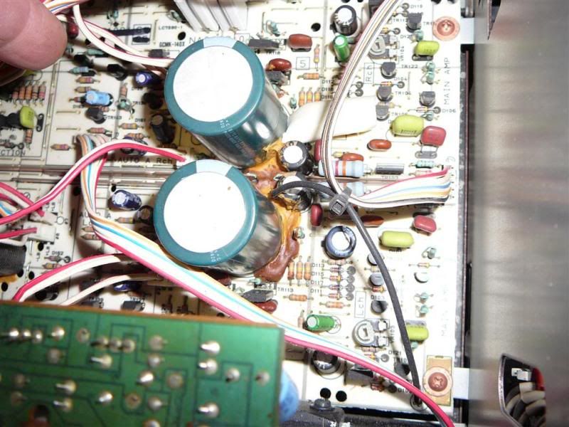
After you figure out which transistor and resistors failed, you might want to check the main board for the Sony Bond Glue issue.
http://www.audiokarma.org/forums/showthread.php?t=345131&highlight=m-80+sony+glue

I'm fairly sure that's what caused my Yamaha M-80 to blow the left channel. Here's a picture of a M-85 with the glue problem.
P1170033Large.jpg

By the way the M-85 is essentially an updated version of the M-80.
 
Hi Avionics,

Of the 8 Sankans on the right channel heat sink, two of the 2SA1169 PNPs have shorted C to E, the other 6 measures OK. The two small driver chips on the heat sink checks out OK.

1) Should I replace all 8 of the Sankans or just the 2 bad PNPs?

2) Where are the 4 Sankan power supply switching power transistors located?
I looked at the power supply PCB but it not obvious to me. I see 3 black
relay on the board.

Thanks again.
If you tested all 8 Sankens you have already tested them. The 4 on the main board are the outputs. The 4 on the small board are PS switching.

I'd start pulling and testing all of the smaller transistors in that channel.
 
1) Should I replace all 8 of the Sankans or just the 2 bad PNPs?

If you find any shorted transistors. Plan on a complete new set of transistors and diodes for the toasted channel.

I'm not just talking outputs. I mean all the transistors in the bad channel. They have all took some major stress.

I'm pretty positive there is still more damaged parts .. bad resistors,transistors and diodes.
 
Last edited:
Here is a typical list of damaged components when and output transistor shorts C-E.
Some may diode check OK but.. They are all within the debris field and have been exposed to excessive current.

TR104,106,108,110,112,114,118,120,124,126
R136,138,152,154,158,160
D112,114,116,118---114 & 118 are zener diodes

I've seen TR102 ( 2SK389BL) take a fatal hit on several occasions.

Each case is a little different .Maybe more parts,maybe less.
Thats why I stated earlier to check all the transistors and diodes in the bad channel.
I print out this shematic on legal pad sized paper and highlight those parts that check bad as well as those that check good. Helps me plot the path(s) of destruction.

http://akdatabase.com/AKview/albums/userpics/10004/Yamaha M80 Schematic with TSB66.pdf
 
Last edited:
Back
Top Bottom