Sansui 8080DB dolby wiring

fbird1969

New Member
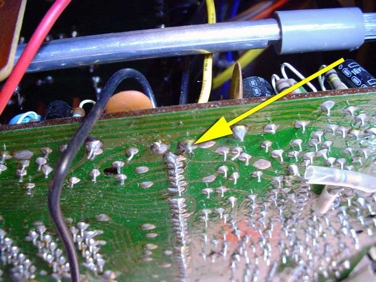
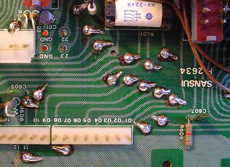
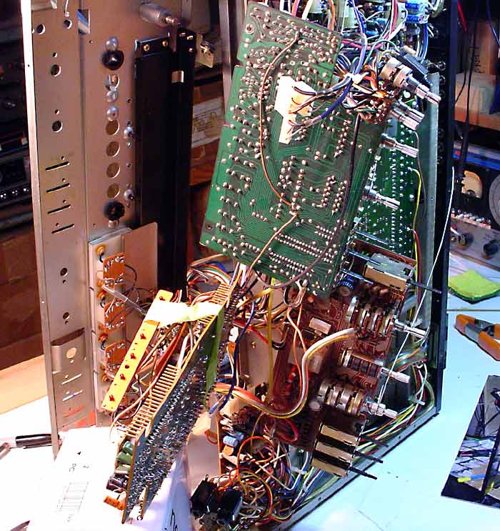
Hoping someone can help me dig myself out of a rookie blunder here. Thx much. I removed my dolby board to resolder the pass-thrus that fail and Unfortunately I created a problem for myself. I had sketched out where all the connections that I desoldered ran between boards, etc. Here's my open issue - I need to confirm where yellow wire # 17 from F-2653 selector board runs to on F-2655 board. I blew it on my sketch. I think it leaves that board on the wiring diagram as a "C" designator that ends up running to board F-2655 Dolby Board but I can't locate what looks like it should be pin or thru hole 701 to connect it to. On the other wire # 18 orange conductor running from the F-2653 selector board, I show it should end up on the F-2654 push button switch board at thru hole 710 if I have it right. Can't believe I botched this up, losing my edge here. So, my issue is the two wires #17(yellow)and #18(orange) routing from the F-2653 selector board to wherever they're actually supposed to end up.

help!
 
On Sansui's, a triple-digit designation generally means an unorthodox connection. Note the number of connections made on the rear of many Sui PC boards...caps, resistors, signal wires, etc. These are generally given three-digit numbers. Such appears to be the case with the yellow wire #17, which connects to the trace that leads to Pin #16 of the NE545B Dolby chip (R01 [1K] also connects here, I mention this as soldering too close to the IC is not recommended).

#18 on the F-2653 is lamp power, 6.1Vac. I have not found the 710 connection designation on the schematic to see if that makes sense.
 
Picture = 1000 words

Just happen to have one laying about ...

f2655-yellow.jpg


Sorry ... ain't about to pull the board so you can see the markings ...
 
Thank you both for the info and the picture - once I have a little rest here this week, I'll dive back in. I think I should be OK now, many thanks! I am running with manually resoldering the pass thrus I could reach ( not re-pinning them) but I'm hearing I may regret that "shortcut" somewhere down the line with all it took to get at this board so far. Any thoughts or experience with this pin through failure?
 
Sorry to say, but you WILL more than likely regret any shortcuts on this repair.

Problem is, the pass through holes have thin rivets in them. Those were pressed in, then soldered, so the actual connection surface is mighty small - just a poor design. Factory had the advantage of new stuff and that's the only reason it took 30 years for these to fail. You can see the rivets in this pic:

f2634-rivets-cu.jpg


What happens is, the solder breaks and the connection goes intermittent. Problem is, new solder won't flow properly under the rivets to get a reliable connection, what with 30+ years of oxidation to contend with. New solder on top looks pretty, but it can't get a "grip" as the copper traces are sealed as well. Basically, you're just throwing a bandaid over the top, even if you DO take the time to desolder and clean each joint. And, if you're gonna do that, might as well throw in a pin, right?

The pinning involves ...

- Desoldering and cleaning each pass through hole
- Scraping back the green sealant off the copper traces about a quarter inch on each side of the board next to each rivet
- Soldering the pins lightly into each rivet with plenty of extra to match the traces
- Bending the pins over each rivet and down tight to the copper traces
- Soldering each pin to the exposed copper traces on both sides
- Flowing each hole for strength, being careful not to move the pins
- Touching up the traces

Here's what it looks like when done (on my 9001 ... same thing, only different):

f2634-pinned-cu.jpg


Anything else is pretty much hit and miss, and even if the "repaired" connections work, chances are good they won't last.

On the bright side, a 9001 has 50+ of those lil buggers, and it's a real PITA to get access to the board. You also have to remove all the switches and relay as things get mighty tight in there. You've only got half that many pass throughs on an 8080db, and they're a lot easier to get to.

Hey, you might get lucky! If you've already got it back together, take a chance, but if you DO end up having to tear it down again ... just sayin' ...
 
Wow - Now I'm starting to understand what asick puppy I am taking this one on. Maybe I should sell it off and let someone else enjoy the fun. I already have a nice Hafler DH-200 ( i built from a kit in the 80's) and Classe' pre-amp I bought years ago, maybe I should be happy and call it a day! Many thanks for all your expertise and picture, looks like some nice work you've done there and now I can understand the rivet physics much better and see why this won't hold forever if even initially.
 
Not trying to talk you out of it ... just sayin' it's a bit more work than what you'd figured to get it right. The receiver is WELL worth the effort, and as long as you're careful and methodical in your approach, chances are real good you'll be happy with the results ...

OK ... one more scary pic, and I promise no more ... <G>

Here's what all it took to get to the dolby board on my 9001 ...

stage-two-teardown.jpg


And might I add ... :yikes: ;-}
 
Back
Top Bottom