
Opened the unit up and started taking voltage readings. I'm using the service manual schematics to find the proper voltages, but i have ran into a different voltage supply than what is stated on the schematics pcb F-2492 shows supply voltage of +15(pin 14) and -15(pin 17) to pin 15 ground. My readings show +29.2 VDC and -29.7 VDC, anyone know if the schematic is wrong or if its supposed to be 15 VDC? The left meter shows input levels when selected to show input level, but when you change the selector to show output level no meter movement. Using my meter on the mV setting i can follow the signal to this pcb with both channels showing input but when i check the outward bound signals from the pcb to the reed switch i only have the right. Thats why i'm concerned with the supply voltage being correct. I plan on using a scope to track the signal later tonight.

You are using an out of date browser. It may not display this or other websites correctly.
You should upgrade or use an alternative browser.
You should upgrade or use an alternative browser.
CA-3000 Left output channel intermittent
- Thread starter cirtcele
- Start date
vigman
SUBSCRIBER
Oh yea... this one is a bit weird....
There are 3 boards for the PS regulators...
You have to get a LONG INSULATED probe and poke down to certian pins
AND there is only 1 ADJUSTER for both voltages ( I believe there is a 3 volt spread between the +/- supplies. 2 20 ish volt and 1 45 ish...
There are 3 boards for the PS regulators...
You have to get a LONG INSULATED probe and poke down to certian pins
AND there is only 1 ADJUSTER for both voltages ( I believe there is a 3 volt spread between the +/- supplies. 2 20 ish volt and 1 45 ish...
Thats where i'm a little confused it looks like the connection diagram is showing the voltage being supplied right off the f-2493 pcb which has no pots. Later i plan on connecting my signal generator to the left aux input 1khz 1v p-p and tracking to find exactly where the signal stops. The other voltages around the unit look ok its just this f- 2492 that worries me.
blhagstrom
Mad Scientist, fixer.
Have the vias (pass throughs) ever been properly repaired on that unit?
If not, you may be chasing your tail for life.
If not, you may be chasing your tail for life.
vigman
SUBSCRIBER
blhagstrom is 100% correct!
I think there re 3 posts in the old thread that you didn't read cirtcele....
here's the first of 3
Ok lets start with something easy....
Pull the boards one at a time..
On mine, the edge connector pins were silver , not gold ( like in the BA ) .
I had really bad tarnish on ALL these pins, used an xacto knife to scrape the male pins and a dental flossing bristle brush ( super micro size ) for the females...
and I used Cramolin as the contact cleaner
That got rid of ALOT of my intermittant issues.
The OTHER issue os on the MAIN mother board, it is double sided....
The thru holes, connecting the top to the bottom corrode away leaving a HI -Z connection or an open...
My " version " had little pins from the factory already soldered in ( phew ) beause there is like 160 of these feed thru's ( YIKES ) and I had 3 or 4 that had cold solder connections. I had additional issues with the meter driver board as well, but my left meter didn't work .. at all..
So lets start SLOW and do some pin cleaning FIRST...
There are ALOT of connectors in there.....
Mike
Last edited:
blhagstrom
Mad Scientist, fixer.
JOMARK,
You did all the feed thru's on the mainboard and a recap in 1 day??
He said one (1) afternoon.... I guess that could be up to 12 hours.
I spent 20 hours on this one.
Well, I did the amp too.
Oh and while I was there, I re-capped and changed out the nasty transistors.
http://www.audiokarma.org/forums/showthread.php?t=523745
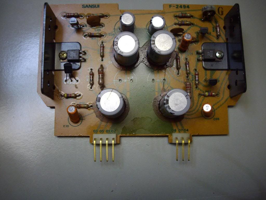
Sorry guys i had to step out to go to a birthday dinner. Just tried the headphones if i turn the level for the headphones all the way up i can barely hear some music. I have been reading some of the old posts trying to get up to speed before i jump in with both feet. The voltage question was one i needed to ask before i went any further.It appears by the photos in vigmans thread that our pcb's are different.Looks like you already replaced the caps. All of the pins in this unit are gold.

Last edited:
JOMARK911
Super Member
JOMARK,
You did all the feed thru's on the mainboard and a recap in 1 day??
Not recap, just the feed throughs , started at 12:00 and ending some time late at night,


Similar threads
- Replies
- 7
- Views
- 790