QRX 9001 Restoration (as in "yet another one")

Spring Planting Season

... is over. That was my main excuse for putting this little project on hold for a while. Hotter than hello outside today, so a good day to stay inside.

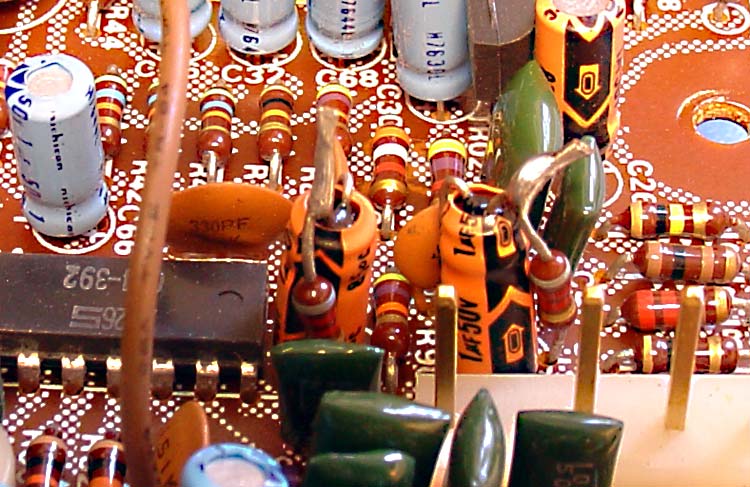
Got started on pinning the switch board. One special tool is turning out to be real handy - I ground the end flat on a small pointy XActo blade and thinned that down for scraping copper traces. I also ground the rest of the sharpened edge so I don't end up slicing and dicing my fingers while working with it.

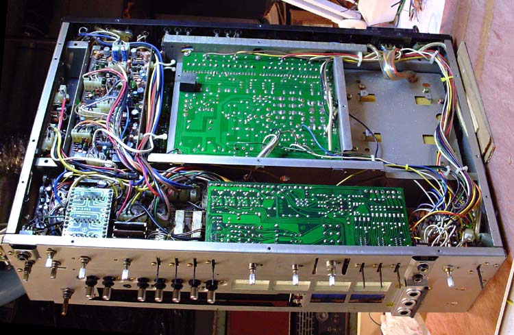
Started on some of the easy to get to pass throughs.

f2634-pinning-01.jpg


One thing I found out real quick - I'm out of practice. Haven't managed to burn thru anything I'm not supposed to yet, and the tin shields are a big help there. Just cut them as needed from some roof flashing and bend them over the sensitive bits.

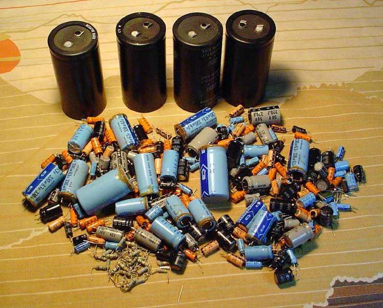
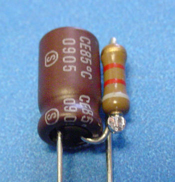
For pins, I used clippings from capacitors that I've been collecting for just this job. I found out fast that it works better if I bend a little "J" hook in the first end. Basically just bend the wire against itself over some needlenose pliers, then bend it back out leaving a small loop that will stand proud of the solder pad. That helps to get the wire flat to the trace.

It's a four step process - for me anyway ...

- Lightly solder the bent wire into the hole, then use my handy dandy XActo scraper to push the wire tight to the trace. The "J" hook makes this easy to clear any ridge around the hole and get a nice tight fit. Also allows you to fine tune the wire so it matches the trace.

- Solder the wire to the scraped trace and top off the blob over the pass through point. Dragging the iron tip back from the blob over the wire gives a nice clean joint.

- Flip the board over, press the wire tight on that side and bend the wire to follow the scraped trace. Solder that same way the front was done. That's another point where that "J" loop on the front is handy - it adds a bit of spring tension to keep the wire tight and properly aligned to the traces on both sides when you reheat the joint.

- Double check the other side of the board. I had a couple joints bubble a bit. A quick touch up with the iron cleaned those up nice.

PS ... thanx everybody for talking me into the 40W Radio Shack desoldering tool. The 30 watter I'd been using wasn't quite hot enough to clean out the big blobs from the old pass through joints. Real easy to work with too.

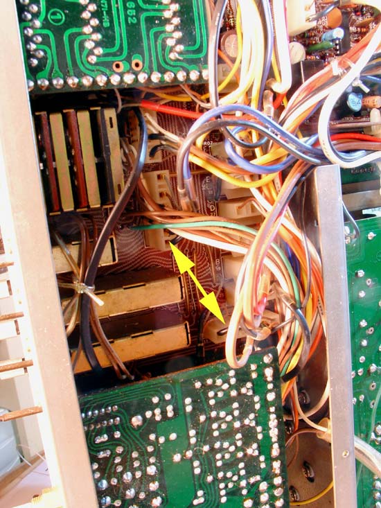
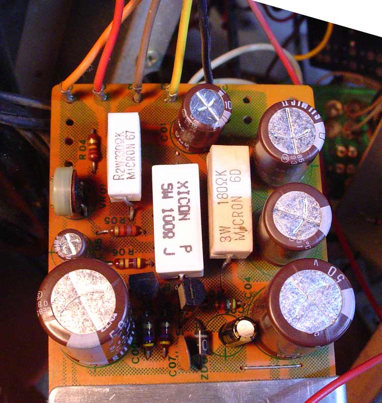
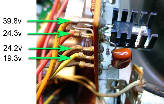
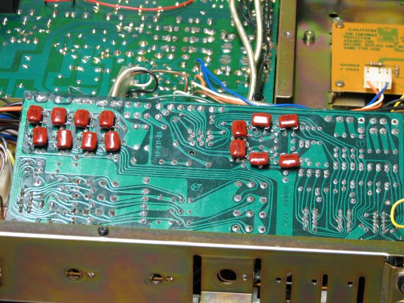
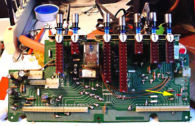
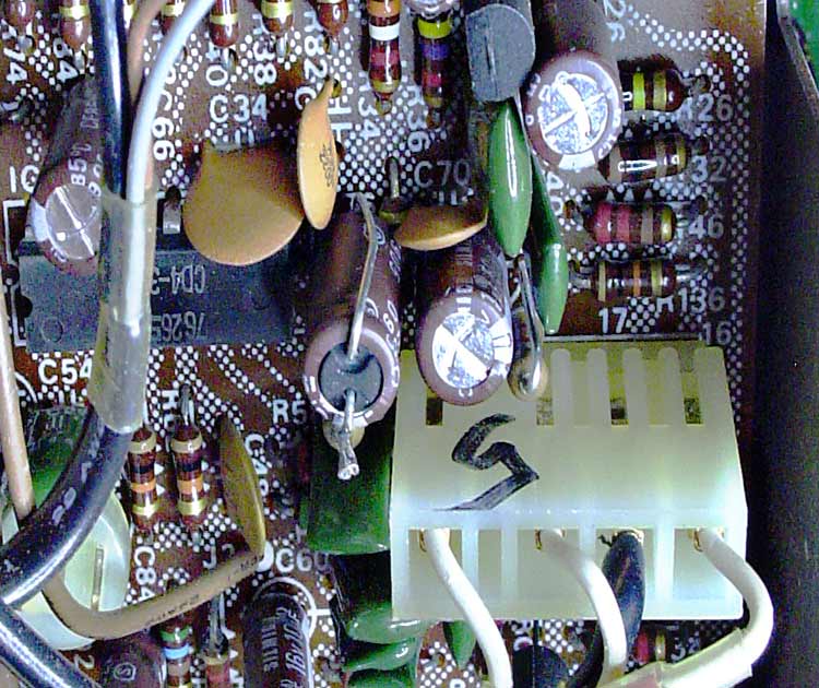
About the arrow ... what the futterwaken is that?? It's soldered on the backside, but I see nothing for it to connect to on the front. One of those Sansui gotchas? As in ... well ... we thought we'd need one there but decided against it? Here's what it looks like from the other side after pinning.

f2634-pinning-03.jpg


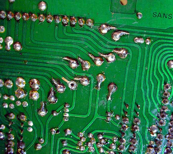
If nothing else, it shows one of the scraped traces ready for a pin. Takes a light touch, so easy does it is the rule. I expect I'll just resolder the blob to nowhere before I pack it up. Still be interesting to find out if anyone else figured it out.

********

13 joints down - and depending on who you listen to - 37 or 39 more to go.

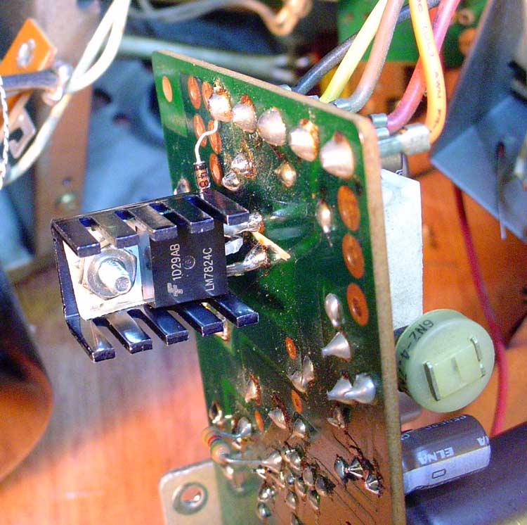
And another PS ... my cute lil holding jig for the board wasn't quite as handy as I thought it would be. It certainly had it's uses, but half the work was done propping the board up with a coffee can.
 
Last edited:
You should be proud of yourself - that is neatly done :thmbsp:

Useful write-up too :thmbsp:

(don't forget to give it a flux clean)
 
Thanx for the reminder ... the can I had went flat. Needed some fader lube too, so I put in an order to Caig.

PS ... in case anyone had trouble picturing the pin shape (I know I certainly did after re-reading my post) here it is.

f2634-pin.jpg

Once one side is soldered, it's easy to press the other side tight to the board. I make the pins all the same size with a needle nose, then trim as needed for the location.
 
Year and a half later ... skipping ahead in the project.

Did all the boards that needed to be done with the front panel off. I strongly suggest copious notes AND photos taken during disassembly to keep you on the path. There's really only one way they can go back together. Double checked the list of gotchas, applied power, and wahoo!! It lives!!

... and let it sit a few more months ... summertime, doncha know. No time to be sitting in the basement ...

Got back into it recently and am now doing the rest of the boards. Currently getting ready to go on the F2589 EQ/CD4 board and noticed these lil rascals:

C71, C72, C75, and C76 - all are mounted upside down and have an 8.2k resistor wired in series on the negative leg of each.

f2589-drop-resistors.jpg


Bit of a kludge job really. Now, I've heard those are there to drop CD4 output to compensate for "hotter" phono cartridges and match it to the other quad modes, but I don't believe I've seen a definitive "keep em or lose em" strategy. I don't do CD4, but not sure what all else is affected. Judges?
 
Speaking of being remiss on updates.

I also did the 25v regulator mod on F2639 for power to the quad boards. Those are known to be quite sensitive to any deviation.

25v-regulator-007.jpg


Here's a good write up on why and what's involved.

http://www.audiokarma.org/forums/showthread.php?t=425109

I also changed the ceramic resistors on the board per Trnsfmr's recommendation.

25v-regulator-100.jpg


Once the mod is completed, you'll want to check all the voltages to the board. Bit hard to read off the schematic ... this should help ...

regulator-volt-check.jpg
 
Last edited:
Oh. The bad with the good, right? Having the beast sit in the basement shop as long as it did apparently drew the little beasties to do the dirty on the faceplate. For anyone who doesn't believe mouse crap ain't caustic ...

faceplate-damage.jpg


Fortunately, somebody else was parting out a unit about the same time and I got a real nice replacement for what I thought was a great price.

We learn from our misteaks, eh. ALWAYS store this stuff properly. And here's a clue - face up on a shelf does not constitute proper storage. <G>
 
I'll get er done eventually ... my biggest problem is that the QRX6001 I'm using for backup is pretty much the same thing for quad goodness if you ignore the watts per channel and dolby, so there hasn't been any great rush. Not a concern here as I drive an external amp for the front channels and just use the rears for ambiance ... For those not willing to go through the pain and suffering involved in restoring a 9001, I highly recommend either the 6001 or 7001 as they don't have the same problems.

(But they're not a pretty either ...) <G>

Don't wait too long - I see prices creeping up on those now that they've been re-discovered.

~~~

So, thoughts on the resistors on the F2589? :thmbsp::thumbsdn:

Not something I'd thought of when sourcing parts. Checked my stock, and I've got 7.5k and 9.1k ½ watt, either of which would be "close enough", but ... I also discovered a couple other items for other projects (rebuilding an AA5 AM tuber radio as well), so what da hey, ordered up some metallic 8.2k ½ watt as well.

Oh. Proof of life ...

reassembly-002.jpg


It all eventually DOES fit back together. I had my doubts considering the extensive gutting. Surprisingly enough, no leftover bits or pieces ... :banana:

What's left can be done with minor disassembly. The F2589 (EQ/CD4) is out now, and the only other board on the bottom is the F2688 (Dolby circuit). Darn shame that Sansui didn't make the dreaded pass through board as easy to get to. That leaves the plug in boards on the top, and I expect I'll be sending the F2624 driver boards into QRX Restore so Jim can work his "holy grail" magic on those.

I also plan to do the bypasses on the F2636 (volume board) but that can be done with the board in place. I've got a hi-res pic that should make that relatively easy ...

2636_with%20bypass.jpg


That shows 600v gumdrops for the bypasses, and apparently those make for a tight fit when reinstalling the bottom plate. Plan here is to use 400v versions that should solve that.
 
Last edited:
Almost forgot ... what 9001 thread is complete without a pic of the finished pin job?

f2634-pinned-cap.jpg


HINT >> If you come up with one short on the total number of pass throughs that require pinning, there's one hiding under the cap indicated by the arrow.
 
CD4 board done ...

More progress. Got the F2589 CD4 board done ... my, that's a lot of caps! This pic shows the original orange caps with drop down resistors.

f2589-drop-resistors.jpg


That was a Sansui kludge job to match the CD4 output to the rest of the quad modes. And here's the (almost) completed board.

F2589-done.jpg


I had some fun with different variations of installing the drop down resistors. This is what I went with:

f2589-drop-resistor.jpg


BUT ... that put the bare leads dangerously close to the pins on the unobtianium ICs, so I went back to the original design. You can see the cap right next to it has my modified install - plenty of clearance there.

f2589-drop-resistors-done.jpg


So maybe Sansui had the right idea after all.
 
Power Rail

As always, the hardest part is matching the cap dimensions to the originals. I came close with these CDE premium caps.

power-rail-done.jpg


Still took a few wraps of Gorilla tape to make for a tight fit in the clamps.

Here's kind of a neat trick to keep things tidy. A lot of the newer caps (including these) have some ridiculously tiny terminals. Real PITA to transfer all the old wire. Nice shortcut is to just snip the blades off the old caps and solder those to the new. Especially handy when there's not much wire to work with. Here's one of the new caps installed with the old blades soldered to the wimpy snap in terminals. Takes the work right out of it.

power-cap-terminals.jpg


And of course, the ever popular poly bypass using a Dayton 0.12uf 250v.

power-rail-bypass-done.jpg


That's to minimize any AC ripple that makes it that far. Basically, the one cap filters the whole rail when properly connected ...

power-rail-bypass.jpg
 
Eventually replaced the incandescent lamps with LEDs, but they're still an option for anyone wants to stay old school. Read on ...

Meter Lamps


Had one out ... good luck finding exact replacements.

Started by pulling the old bulbs and noticed one terminal post was loose on the board. Trace was broken, so the "bad" bulb wasn't bad after all. I reinforced the trace with a good solder bridge ...

meter-lamps-(1).jpg


... and followed up with some hot glue. Not the prettiest repair in the world, but strong ...

meter-lamps-(2).jpg


Long as I was into it, went ahead with the bulb replacement using these:

Wedge Base Lamp 8v 300ma
http://www.vintage-electronics.net/wedge-base-lamp-8v-300ma.aspx

Pop the old meter lamps and you'll see the original bulb is threaded into a rubber base. Pry the wire out from the bottom with a thin blade, pull the lamp straight out, and reuse the base for the new wedge base lamps. Here's the various stages:

meter-lamps-(3).jpg


So, what's wrong with that pic? I did a dOH! You have to pry the wire away from the base of the wedge lamp and cut it so you can thread it into the old rubber mount. Careful to cut the INSIDE wire on each loop - cut the outside wire, and you kill the bulb as that end is just fused into the glass for reinforcement. Lucky me, I'm used to being Polish, so I got spares.

The wedge bulbs just press fit nicely into the flexible base, then carefully thread the wires the same way as the original bulbs. Last stage ... install the "new" bulbs in the light board. They do stand taller than the originals, but there's plenty of clearance. Hard to tell in the pic, but there's a good half inch between the bulb and any part of the meters.

meter-lamps-(4).jpg


Color temp and brightness are quite close to the originals, but there IS a difference. I expect you'd want to replace both meter lamps at the same time. "Hot" spot in the meter face isn't any worse than original, but I may look into adding some sort of diffuser panel to get a better spread.
 
Last edited:
LED Lighting

The infamous PLAN B strikes again.

Stumbled across these for landscape lighting or car bulb replacement. Rated AC or DC at 8-16v, so I picked up a pack and gave them a go. I mean ... what's the worse that could happen?

zzzzzzzzzzZZZZZZZZZZTTTT!! <G>

led-lighting.jpg


Not too shabby! Plenty of light at the reduced voltage, with a good wash across the faceplate, and less of a hot spot on the signal meters. No flickering at all, and no changes required to the power supply - truly plug 'n play. Same mods using the original Sansui bulb sockets that I did with the incandescent bayonets, except for I razored off the cupped part that fit the original round bulbs. You can see the difference in the signal meter bulbs pictured above.

The bayonet base pops right off after you bend the wires away. Bonus ... the original blue green bulb shields clipped right onto the LEDs. I did add a small spot of hot glue to hold each bulb assembly together.

Here's the LEDs ... $10 for a pack of 10.

41UOoSndYbL._SY355_.jpg


Zone Tech 10x WARM WHITE High Power LED Car Lights Bulb
 
Oh, you mean I'm not talking to myself? Good to know ... <G>

Yah ... no changes at all to the original lighting circuit. The modified bulbs mount exactly the same way. As mentioned, I was able to use the original color shields for the dial lamps, so no problems matching the original hue using the warm white LEDs ...

led-lighting-dial-shields.jpg


UPDATE

One change coming on the LEDs ... they DO have a very slight flicker to them, something that would be easy enough to ignore, but ... I found a nice little AC/DC adapter on da bay that's pretty much plug and play. Just clip the VAC leads into the meter light board and hook them back up with the box in place.

!Bh,eg9!!2k~$(KGrHqIOKjIEry,U1i(ZBLJCcWZ(3Q~~_35.JPG


I'm leaving the original power meter lamps in place as I understand those can be a real PITA to get out and they're working fine. I can snip the leads from the light board (which would now be VDC) and attach those to the original VAC power leads prior to the LED adapter.
 
Last edited:
Wonky IO ... Huh?

Problem with getting close to done is it gets hard to stay on it. My excuse right now is spring planting. Rainy day, so down in the shop.

Noticed last time that Tape ONE wasn't working at all. I could just barely hear it way back in the weeds if I tweaked the volume up. Also had some strangeness on Tape TWO ... that's the four channel loop, and it seemed like the rear channels were reversed?

Fortunately, found the problem first place I looked. Tracked down the other end of the connector that's directly behind the Tape ONE switch - that wandered off to - you guessed it - the rear channels on Tape TWO. Easy enough to spot a similar connector, and sure enough, that hooked up to Tape ONE.

Simple swap, and all is well. All signal level, so not much chance of blowing or stressing anything else.

f-2636-reversed-connectors.jpg


Good example of why we need to make good notes along the way. There's a long row of connectors that I did mark alphabetically to match what was printed on the board, but assUmed it'd be pretty hard to screw anything else up. Bad assumption on my part making for a good amount of unnecessary head scratching.
 
Lighting mods done ...

Went ahead and adapted the meter and dial lamps to VDC using the LED rectifier I mentioned earlier. I clipped the leads from the lighting board for the power meters as those are still the original VAC bulbs. I've heard some horror stories about changing those out, and they're working fine as is, so best left alone. I also didn't want to run those on VDC as I've heard issues with the filaments blackening if you try it.

The rectifier is just mounted to the chassis using 3M body molding tape.

LED-adapter-cu.jpg


There's two sets of leads for the power meters that were lengthened and tied in on the AC side of the LED regulator. Easy enough to switch if I ever feel the need to go LED on those as well.

I'd forgotten about the tinted glass over the dial, so it turned out a bit dimmer than the earlier pic. Still has a nice even wash all across the dial - a BIG improvement over the original incandescent lights.

front-panel-lit4.jpg


I still may play with the tuning meters and try to tone those down a bit. I've got some limo window tint that works wonders for that.
 
... and as my good friend Elmer Fudd always says ...

ba de ba de ba dee ... That's All, Folks!!

One last round with the VOM, and I've got four clean channels with next best thing to 0 offset and the bias dialed in at +/- 3mA per the book. Put it through the paces in all modes and rock solid IO - can't say I'll miss the intermittent "spin the wheel and see which channel disappears every time I push a button. Ran it up to moderate levels and let it go for a couple hours on the bench and no issues, so ...

Couple coats of wax on the case, and buttoned it up.

completed.jpg


completed2.jpg


All that's left now is to drag it upstairs and plug it into the system ... Gotta admit, after all that went into getting this done, that's gonna be a magic moment!
 
Oh ... almost forgot ... what QRX 9001 restoration thread would be complete without the obligatory Big Ol' Pile o' Parts pic ...

pile-of-caps.jpg


And I heartily agree with a bunch of other comments on restoring one of these things ... it was fun once, but NEVER AGAIN !! ;-}
 
Back
Top Bottom