AU-517 Restoration Questions

Thanks for the clearing that up John! Everything is going smoothly, removing the glue, double checking values...

One thing that's got me stumped is the EQ board (F-2723). Is there a trick to getting it out?

Those ribbon cables to the RCA inputs look like no fun. Do you just remove both boards?

Thanks,
Jonah

Hi Jonah,

On all of the 417/517/717's that I have done, I didn't completely remove the equaliser board. I'd I'd it this way -

Remove front panel
Remove the two switch shafts from the front panel and the switches

Remove the board bracket to chassis mounting screws, and the unplug all fo the cables that plug in. the equaliser bosrd can then be carefully lifted up enough to get access to all of they older joints of the component that need replacing. I have done a dozen or more amps this way Jane never had a problem.

There are other ways of doing this such as removing the board completely by unsoldering the ribbon cables as well.

Cheers

John
 
I pop the plastic pins out on the back and remove both of those boards. The plastic pins are available from Mouser. Putting in new shiny ones help the looks too. That only leaves one wire to unsolder, the ground on the lug. After that every board can be laid out on the table in front of you, makes it a lot easier.
 
A few things I'm grappling with....

Right on... I think Ill try snaking the EQ Board without removing the input board. I do have a bunch of work to do on it, so if it seems like a pain to access the components, the whole ribbon cables and/input board are coming out!

A few things Im grappling with...

- If I step up to Nichicon 63V 15000uF chassis caps, should I change the value of the small caps bridging the solder lugs? If so what value? It is currently 105k 100V.

- Also these caps seem to be Metallized Polyester Film. Is this what I should stick with?

- Is there a part number or modern equivalent for the grey push on connectors found throughout the AU-517?

- My power cable is a bit chewed up and wanted to replace it. Is there a benefit to putting in a grounded plug? If so, where in the amp is the ideal grounding spot.

Thanks in advance!!! Im getting there slowly. First amp restoration and I appreciate everyones time and patience.

Jonah
 
Grounding

Thanks for the link Karl. I checked it out earlier and was thinking something similar, but I was curious to know where to ground the AC plug to. There wasn't an obvious location and no mention of it in the post.
 
The obvious place to me is the closest bolt that holds the transformer down. I always put a ring terminal on the green wire and put it on the transformer bolt when I reinstall the transformer. I remove one to get to the last screw on that one board.
 
I did it, too.

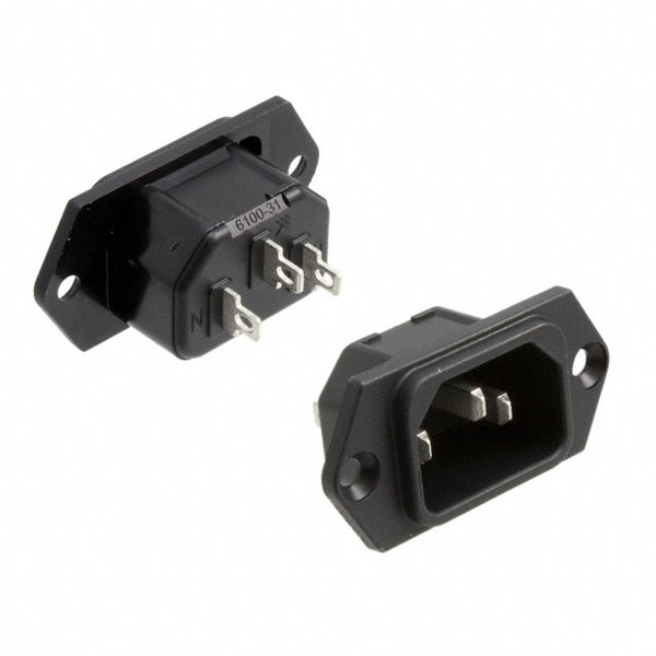
Just wondering how difficult would be an inlet socket... :scratch2:

Schurter-6100.3100.jpg
 
It's not too hard, but time consuming. Cut a small hole with a dremel tool and enlarge to fit with needle files. Mark screw holes when the body fits in it's hole. Or just matedrill the holes.
 
F-2670 Caps

Hmmm... IEC...

Do you guys replace the Electrolytic Caps on the Pre Main Switch Board F-2670?

If so, how do you deal with the small pop rivets? Is there a readily available replacement part that works for putting the panel back on the chassis?
 
Hmmm... IEC...

Do you guys replace the Electrolytic Caps on the Pre Main Switch Board F-2670?

If so, how do you deal with the small pop rivets? Is there a readily available replacement part that works for putting the panel back on the chassis?

For me Yep:yes:

I slowly push out those blk plastic pins from internally, ltr part wld be the pin housing.

Inside those r 4 orange 10uf/25v caps. I use Nichicon KL series to swap it.

Also unsolder the pre/separate switch to ply the side pin out to hav a cleaning/deoxit lube of its rails.

Aft install back the same procedure as before.
 
Almost there!

- Is there a reason that the VD1212 diodes are elevated off the boards? As I replace with two 1N4148TA diodes in series, should I elevate them as well?

- Besides the Bias Current and Voltage at speaker terminals, are there any adjustments to variable resistors etc. that should be done during a recap/VD1212 restoration while I have the boards out?

Should have this thing together next week. Will post pics as soon as its up and running.
 
Almost there!

- Is there a reason that the VD1212 diodes are elevated off the boards? As I replace with two 1N4148TA diodes in series, should I elevate them as well?.

I would only elevate them slightly off the board, they must absolutely not be 'tight' to the board. I would leave around 1/4" between the diode body and the board.

- Besides the Bias Current and Voltage at speaker terminals, are there any adjustments to variable resistors etc. that should be done during a recap/VD1212 restoration while I have the boards out?.

Not quite sure what you mean here, you will be adjusting all the trimmers when you have the unit powered up? Have you fitted new trimmers? (you should).

Should have this thing together next week. Will post pics as soon as its up and running.

Ok - looking forward to that...
 
C37/C38 on Eq Board

Just ordered new trimmers for the driver boards! Thanks for the heads up.

- Do you typically replace C37 and C38 on the EQ Board (F-2723)? I couldn't find the specs on these in the service manual or elsewhere... Not sure of type or value? Also, werent listed in a couple supplementary cap. lists for the AU-517.

So close!!

Yr listed C37/38 i cldn't recall whether it an ecap or square mylar caps.

But if an ecap just replace as the same spec to original.

As for those square mylar i leave them alone unless obvious bloat found.

Refer to yr board for their types imo
 
End is in sight but some quirkiness...

So it's xmas morning and somehow Ive found the time to get the 517 put together. Things came together well; however, I have a couple of issues...

Part I
When I first put it together, I had distortion on both channels and couldnt get a bias reading at the test points. I quickly discovered that I had replaced the fusible resistors with the wrong values. On the driver boards I had replaced them with 82k instead of 82 Ohm and on the EQ board, 150k when they should have been 150 ohm.

To remedy this, last night I swapped some 1/4W carbon comp resistors in while I wait for the new parts. This sounds much better (kinda great even), but Im noticing some quirkiness with the bias setting and Im sure something is off. When I setup the machine as per the service manual (volume down, warmed up, set to Aux) the reading seem to vary wildly...

Speakers OFF
L Chan. - 12.5 mV (very un even thrown on trimmer 0 mV - 160 V+)
R Chan. - 0 mV (no change when using trimmer)

Speaker A
L Chan. - 12.5 mV (very un even thrown on trimmer 0 mV - 160 V+)
R Chan. - 0 mV (no change when using trimmer)

Speaker A (Speakers Connected)
L Chan. - 20 mV (large range from 13mV up to 160 mV+)
R Chan. - 21.5 mV (no lower than 21.5 mV and up to 160 mV+)

Speaker B
L Chan. - 12.5 mV (very un even thrown on trimmer 0 mV - 160 V+)
R Chan. - 0 mV (no change when using trimmer)

Speakers A + B
L Chan. - 12.5 mV (very un even thrown on trimmer 0 mV - 160 V+)
R Chan. - 0 mV (no change when using trimmer)

Im hoping my mistake with the resistors didnt damage a transistor or something down stream. This being my first restoration, Im curious to know if you all have any thoughts on what might be causing this weirdness. Is it normal? Should I worry?


Part 2

There is a low hum when I use the Phono 1 input. Inaudible when playing music. When I switch to Phono 2 with no source plugged in, there is a much louder hum. Is this normal? Maybe just poor grounding somewhere?


Best and happy holidays!
Jonah
 
Go wif metal film for those fuse resistors.

I oly gt to measure though spk A output to tune the offset close to 0mv n bias though the test pin at driver board at 20mv.
 
Back
Top Bottom