robbe_15
Member
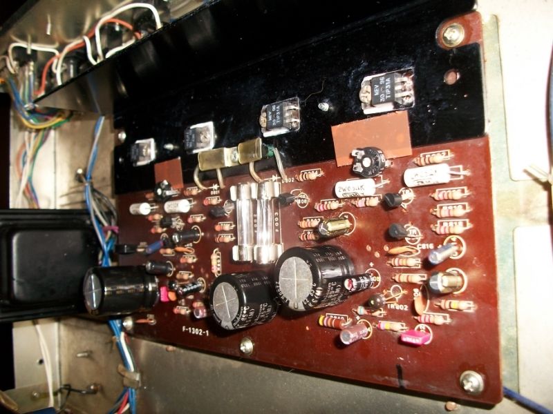
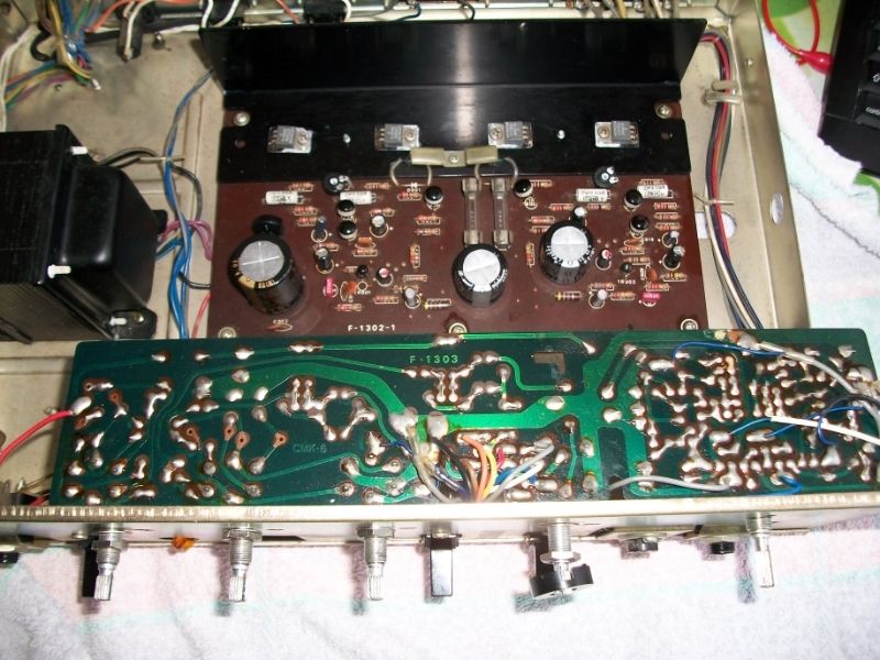
Recapped a AU-101. Foto….. work in progress.
Put in trimpots (500Ohm) for adjusting BIAS.. according info found on this site.
Measured across one emitter resistor left = 10mV = OK, right = 70 mV can not go lower. Same values reached as before recap. Output transistors of right channel are slightly warmer then left but you can still touch them, so not so hot.
Is 70 mV acceptable for a cap coupled amp or is it time to replace flying saucers transistors wich are still in place ? Soundwise it seems to be OK. I notice almost no difference between the two channels, maybe left (distorted channel) more bass but not very clear.
 thank you for good tip !