Repairing QRX-7500 Receiver

Crimped pins ... as in pins that are crimped ... <G>

25v-regulator-bypass.jpg


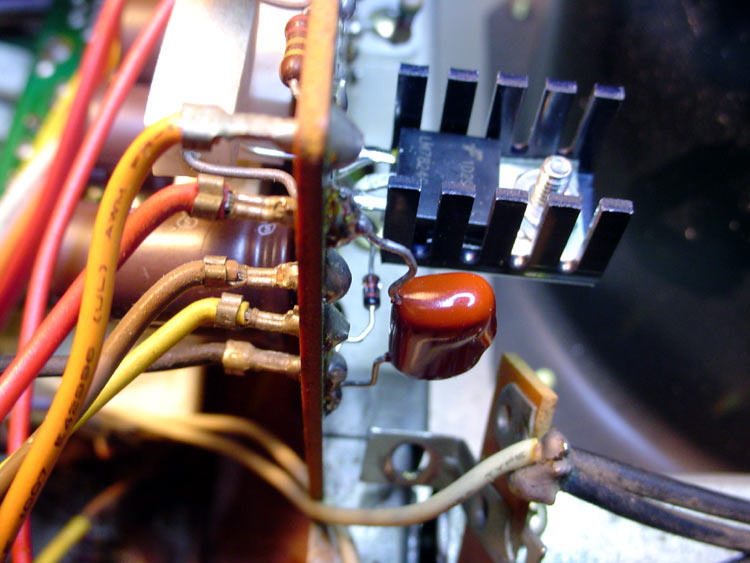
There are exceptions, but that was fairly typical for most Sansui point to point connections, at least on the larger gauges. Easier in the factory to just jam them in the holes as they're a fairly tight fit and will stay in place for soldering. Reworking them does require a very good cleanup of old solder so the pins will still fit without having to force them.

No pins, no worries. Less heat required on rework, and less chance of lifting traces. Still gotta be careful with old boards.

Pics you've been posting are fine. Photoshop or a similar editing program is handy. The one above is a detail closeup and only 78kb, down from an original of 1.6mb or thereabouts, so you CAN get some good quality shots that don't take up a lot of space. Of course, having your own website has a decided advantage, but there's a lot of photo share sites like Flickr that are quite popular for larger shots and limits.

If you DO decide to de-wire the board for complete removal, Good pics are a must for later reference. I also tag the wires with numbers going left to right, and bottom to top if there's more than one vertically. Your power board has a lot of wires, so another trick is to do a grayscale pic on a BW printer, then mark that with white out and a sharpie. Still way more work than I'd want to get into if it wasn't necessary.
 
Thanks for your photograph. My power supply CCA has only five or six large wires that look like they have some sort of band crimp around the wire and the pin. Then the wire and band were soldered together. I intend on de-soldering one of them to see how much trouble it is to get the crimped band off. So we have slightly different terminals. My terminals are more of a straight, round pin and not nearly as bulky as the ones that penetrate your board.
 
Method of changing dial illumination and mode lamps

The QRX-7500 chassis has four of those fuse type of lamps behind the radio dial. The bulbs are not accessible unless the white hood is unscrewed and moved rearward. The screws that hold the hood in place are easily accessible from the top of the chassis. To make enough room to move the hood backward, the long, black metal circuit board holder behind the hood needs to be loosened up and tilted back a bit. This gave enough room to pull back the dial illumination hood and get to the bulbs inside. I took a picture of the illumination hood in one of the photos while it was pulled back and then upward. Once in this position the bulbs can be removed with your fingers.
The mode lamps that show you what mode the receiver is in are all mounted at the top of the dial illumination hood in round cavities. They all have a rubber seating gasket on them that allows easy removal; they just pull out toward the rear with your fingers. The bulb in the second photo that's been pulled out of its holder is the FM mode indicator. The bulb looks good (not burnt inside), but it doesn't light up. I measured the voltage while changing modes from Phono2 to FM and it measures about 6.5 volts, which means the bulb should light if was good; so I'm assuming the bulb needs to be replaced. I'll try re-flowing the solder at the bulb wire connections first to see if I may have a corroded solder joint. Either Sansui didn't clean their boards well, or the flux is oozing out of the joints over the past 40 years. Either way, I'm leery of the quality of the solder joints so I must try re-flowing the solder before swapping out the bulbs.
 

Attachments

  • Dial Illumination Hood.JPG
    Dial Illumination Hood.JPG
    198.4 KB · Views: 24
  • Mode Lamp Replacement.JPG
    Mode Lamp Replacement.JPG
    201.6 KB · Views: 21
FM Stereo Indicator Light

How decent of a FM antenna do I need to get the FM Stereo indicator to light on my Sansui QRX-7500? I have a 20 gage, three foot piece of stranded wire stuck in the FM Antenna terminal and I get plenty of stations and signal being indicated on the analog meters, but the FM Stereo light doesn't ever come on. I checked the bulb continuity and even swapped out the bulb but it still doesn't light. Do I need a better antenna, or does anyone think it could be an alignment issue with my receiver?
 
How decent of a FM antenna do I need to get the FM Stereo indicator to light on my Sansui QRX-7500? I have a 20 gage, three foot piece of stranded wire stuck in the FM Antenna terminal and I get plenty of stations and signal being indicated on the analog meters, but the FM Stereo light doesn't ever come on. I checked the bulb continuity and even swapped out the bulb but it still doesn't light. Do I need a better antenna, or does anyone think it could be an alignment issue with my receiver?

FM needs a full loop to work properly. A cheepo 300 ohm "T" dipole should be good for testing. And there's TWO connections required, either 300 or 75 ohm depending on your antenna ...

21oAQsjikrL.jpg


Ratshack, most any store with an electronics department, or easy enough to make your own ...

Are you getting a stereo signal? The light should go on as long as you've selected FM AUTO and have the meter centered as long as you have a decent signal. I get a full meter on most stations from 30 miles out, but I'm using a slightly better antenna than your 3 foot piece of wire ... :D

fm-antenna-stack.jpg
 
Are all of the Sansui CD-4 Adjustment records the same?

I'm about to try my old Dual 510 CD-4 turntable with the Sansui QRX-7500 (now that I have all four channels working). I remember when I had my stand-alone Sansui QC-04 demodulator in the 70's, it came with a Black "floppy" Sansui 45 RPM adjustment record. So now I have a different situation: I'm trying to use the built-in CD-4 demodulator in the Sansui QRX-7500. Does this receiver require the same record or a different record to adjust the carrier and balance? If anyone knows, please reply. Thanks!
 
Any of the CD4 test records will work using the same setup. I use a JVC record myself.

First off, balance all the channels for max output with minimal distortion using the 30kHz test tones, then you run through a series of tracks that are used to balance channel to channel across each plane of the room, then diagonally.

Keep in mind, none of this is necessary unless you have CD4 encoded source material. I think I got maybe a dozen out of hundreds of vinyl here. QS and SQ are encoded, but use a totally different system that's not as picky about setup. Amazing how much "stereo" material was actually recorded using one or the other systems. Of course, the synth modes will work with anything.

I keep my system mostly on SQ for rock and pop unless I know it's encoded as QS. Working my way through Toscanini's The RCA Years collection right now, so it's pretty much locked into HALL, as that's my mode of choice for the older classical recordings. Anything mid 70's to the bitter end is more than likely SQ - plays back fine on stereo equipment, so it was no extra effort to just cut it that way once they'd invested in the equipment.

Basically, experiment and have fun!

* I see Discogs has several for sale at less than $10 a pop ...

http://www.discogs.com/search/?q=cd4+test&type=all
 
Last edited:
Thanks for your reply. I was referring to setting up the built-in CD-4 demodulator on the QRX-7500. I may sell my receiver with my old Dual 510 CD-4 turntable and Pickering XUV-4500 CD-4 cartridge and the four channel records. I think if I sold them together and the demodulator worked I could get a good price for the "set". The receiver needs to be re-capped and I don't have time to do all of that work. At lest all of the channels work now.
To tell you the truth, when I had my old QRX-3500 in 1975 through 2010 I would leave the four channels on in one of the synthesizer modes (can't remember which setting) so that I always had sound in the rear speakers. The sound was always fantastic. It's always better when you're the 1st owner of the receiver. Nothing to fix!!
 
Hello,
I am wondering if there was a model number on the QRX 5500 pot you installed. I bought a 5500 with the same issue you repaired. I'm looking for a replacement level set pot and a knob. Any info on this pot is helpful. Great post BTW.

Best,
Fred


Level Set Pot Removed. Rear pot completely fractured.

I finally removed the original Level Set pot from my Sansui QRX-7500 and found that the Left Front pot (the one at the very back) was completed broken up inside. I took a picture of it after I removed the back plate. I also took a photo of the control pot I was sent from hybridrestore.com. I wrapped each pot section with a 3/16 inch piece of electrical tape to protect it from splashes of solder while I make the repair. BTW, A long time ago, I bought a small, Red, plastic suction cup type of vice from Radio Shack. That vice has turned out to be one of my best investments. I used it this evening to hold the replacement control pot while I unsoldered the short wires from it. They guy that sent it to me must have just clipped the wires in the QRX-5500 he removed it from.
While I was in the process of replacing this control, I decided to also replace the fuse style lamps behind the VU meters. Two of mine were burned out, so I bought some on e-Bay that are exact replacements. I got five bulbs for $16.00 including the shipping.
 
Here's another example ...

f1363-tone-block-original.jpg


As you mentioned, the electrical contacts are in the back section of the switches. If you operate the switch, you should be able to see the rocker moving there, and that gives you a good idea where to spray the cleaner. There's holes scattered about in the case to allow access. I use short bursts of D5 on low pressure and operate the switch several times, let it sit, and repeat. Careful for overspray and drips, and use no more than needed.

I wouldn't lube the mechanical section if it's working ok. Lube draws dust, and that's what kills em.

Don't know if you've got any of the long type Sui switches ...
daughterboard-off.jpg


With those, you'll see a hole on the switch at each contact point. I use a needle bottle with D5 and just put a drop in each hole and work the switch several times to spread it around. Always let them drip out and dry overnite before applying power.

PS ... you may be tempted to try disassembling the switches for an uber cleaning ... don't ... just don't ...
Hello, I haven't talked with you in years. Are you still a member of this forum?
 
Hello, I haven't been on this forum in years. Are you still a member? I tried to look you up but didn't see you listed as a member.
 
Back
Top Bottom