Kenwood Basic M1 Power Amplifier Restoraton/Upgrade

Leestereo

Super Member
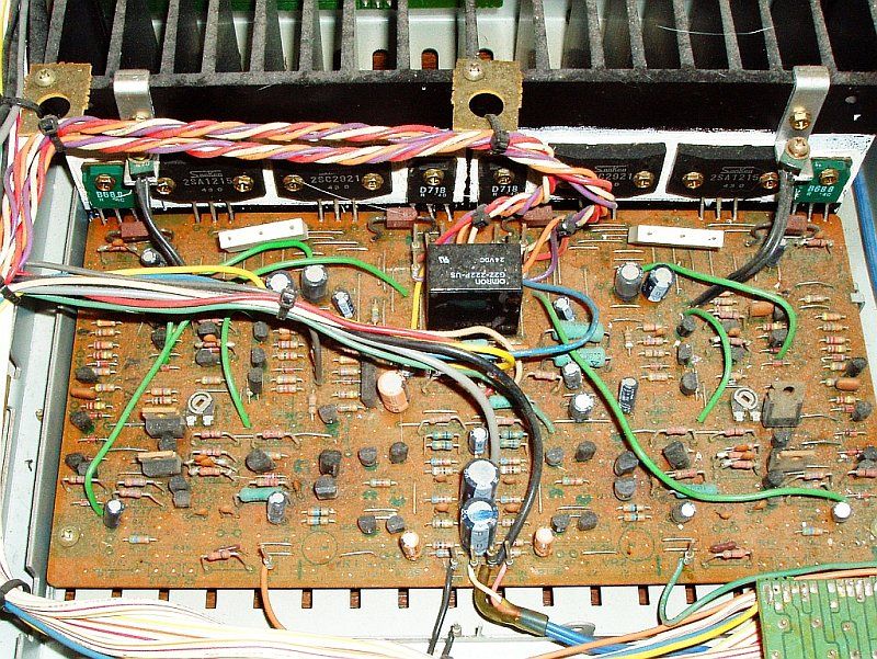
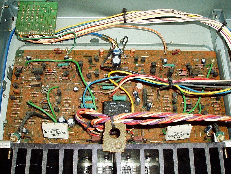
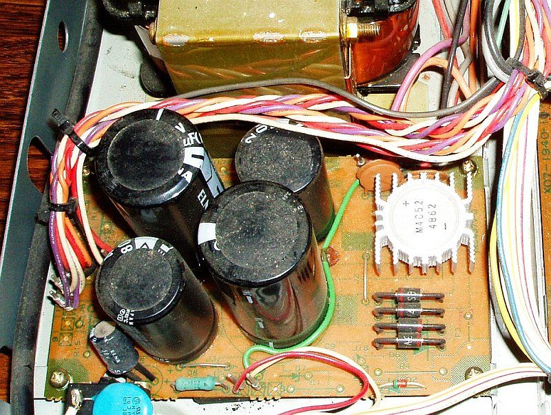
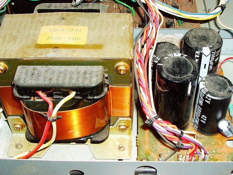
AK member Unican Eric brought in this Kenwood M1 for a complete restoration and upgrade. The M1 is a well regarded 105 wpc power amplifier from Kenwood's Basic series and definitely merits a restoration/upgrade. The restoration/upgrade plan for this Kenwood M1 consists of the following:
1. Replace all of the power supply electrolytic capacitors with higher spec. 105°C low ESR types (increasing capacity where appropriate and possible).
2. Implementation of the DRM Audio Kits' current source modification.
3. Installation of emitter degeneration resistors for the input differential pair.
4. Replace the signal path capacitors, with either film types or C0G/NPO types, as appropriate.

Here are some pictures of the Kenwood Basic M1 power amplifier as first received:


Last edited:
Gotta watch this one as I have one I'll be checking out later. Need a new relay first to see if I can get it to power on.
 
Power Supply Board

The original capacitors were 6800µF/42V in the low voltage supply and 7500µF/71V in the high voltage supply. Due to the limited amount of space on the power supply board, the maximum diameter for the replacement low voltage capacitors is 25mm; similarly, the replacement high voltage supply capacitors can not exceed 35mm. These size constraints also limited the capacity increase of the replacements to a relatively modest amount.

The original 6800µF capacitors in the low voltage supply were replaced with 8200µF/50V Panasonic low ESR, 105°C types. The 6800µF capacitors used the standard 10mm-spaced snap-in terminals, so replacing them was straight forward once the too-generous amount of old glue was removed.

Replacement of the original 7500µF capacitors in the high voltage supply was somewhat more cumbersome since they used a now obsolete 3-pin arrangement with 15mm spacing between the live terminals. The replacements for these capacitors were 8200µF/80V Panasonic low ESR, 105°C types. These capacitors had 4 "snap-in" pins with 22.5mm spacing between the live terminals; once the 2 dummy terminals were removed, the live terminals can be adapted to use the extra lug terminal solder pads that are available on the board.


Last edited:
Input Stage

1. Signal Path Capacitors:
The stock capacitors in the input high-pass filter (C1, C2) were 4.7µF low leakage electrolytic capacitors and these were replaced with 1.0µF Panasonic stacked polyester film capacitors; the F3 of this high-pass filter is ~1.6Hz.

The stock capacitors in the input low-pass filter (C3, C4) were ordinary 100pF ceramic capacitors. These were replaced with C0G/NPO capacitors of the same value. The F3 is 2.3MHz (a low-pass should have a F3 of at least 1.5MHz to have minimal phase shift at 20 kHz). The C0G/NPO capacitor type is a Class 1 ceramic capacitor with excellent properties: they are very temperature stable (0 ppm/K); have very low electrical losses with a dissipation factor of ~0.15%; and no performance degradation with age. Their performance is comparable to polypropylene film capacitors, but their small size affords greater flexiblity for their installation in older equipment.


2. Current Source Modification and Emitter Degeneration Upgrade
The differential input pairs (Q1/Q3 and Q2/Q4) in the M1 uses a simple 56k resistor (R17/R18) as a current source, whereas its M2 bigger brother uses a better performing active current source circuit. Dan Mattis of DRM Audio Kits has developed a nice and compact upgrade which gives the M1 an active current source by replacing the 56k resistor with a LM334Z adjustible current source IC. With a 150 ohm resistor installed on the LM334Z, the current at the differential pair measured ~470µA. With this increase in tail current over the original current of 328µA with the 56k resistor, I noticed that there is now the opportunity to add emitter degeneration resistors to the differential pair by replacing the jumpers at R11/R13 and R12/R14 with 47 ohm resistors (the current at the differentials will then be back to the original value of 328µA). These resistors provide local feedback and improves the input stage linearity.


Last edited:
Input Stage

1. Signal Path Capacitors:
The stock capacitors in the input high-pass filter (C1, C2) were 4.7µF low leakage electrolytic capacitors and these were replaced with 1.0µF Panasonic stacked polyester film capacitors; the F3 of this high-pass filter is ~1.6Hz.

The stock capacitors in the input low-pass filter (C3, C4) were ordinary 100pF ceramic capacitors. These were replaced with C0G/NPO capacitors of the same value. The F3 is 2.3MHz (a low-pass should have a F3 of at least 1.5MHz to have minimal phase shift at 20 kHz). The C0G/NPO capacitor type is a Class 1 ceramic capacitor with excellent properties: they are very temperature stable (0 ppm/K); have very low electrical losses with a dissipation factor of ~0.15%; and no performance degradation with age. Their performance is comparable to polypropylene film capacitors, but their small size affords greater flexiblity for their installation in older equipment.

What voltage rating were the 100pF caps you used? Also, did you go with 1uF on the high pass just because it was small enough and you wanted to use film? I have both Panasonic ECQ 1uF/50V stacked film and 4.7uF/25 and 50V Nichicon UKLs.

2. Current Source Modification and Emitter Degeneration Upgrade
The differential input pairs (Q1/Q3 and Q2/Q4) in the M1 uses a simple 56k resistor (R17/R18) as a current source, whereas its M2 bigger brother uses a better performing active current source circuit. Dan Mattis of DRM Audio Kits has developed a nice and compact upgrade which gives the M1 an active current source by replacing the 56k resistor with a LM334Z adjustible current source IC. With a 150 ohm resistor installed on the LM334Z, the current at the differential pair measured ~470µA. With this increase in tail current over the original current of 328µA with the 56k resistor, I noticed that there is now the opportunity to add emitter degeneration resistors to the differential pair by replacing the jumpers at R11/R13 and R12/R14 with 47 ohm resistors (the current at the differentials will then be back to the original value of 328µA). These resistors provide local feedback and improves the input stage linearity.

Is this the correct part?

If so, which legs go into the resistor holes from the 56K ones removed? EDIT: Just looked at data sheet, legs V+ R V-, does "polarity" matter here since it doesn't with a basic R?

What is done with the third leg of the transistor?

Which legs of the transistor get the 150ohm Rs strapped across?

EDIT: I guess both questions above are together. the 150ohm R goes from the middle leg to the V- leg correct? Again, reference question 1.

What wattage rating Rs are you using for all the above 1/4W? If so, are 1/2W OK also?

Sorry for the questions, but I couldn't quite make out the info from the angle of the pics. Great labeling of your shots though.
 
Last edited:
In this particular case, the C0G capacitors used were rated at 100V, but one can use 50V parts as well. A 1µF stacked film capacitor was used for C1/C2 since it fit the available board space well and the F3 was more than sufficiently low (with a film capacitor, a F3 of <5 Hz is desired).

I've attached another picture which shows the L334Z with the resistor better. Yes, 926-LM334Z/NOPB is the correct part at Mouser. The resistor sets the current level and is connected between the middle ("R") leg and the "V-" leg; a 0.25W part was used, a 0.5W can be used but may be a bit large physically. The orientation is important for proper operation: on the left channel LM334Z is oriented with the flat surface towards the front of the M1 amplifier. On the right channel, the LM334Z is oriented the flat surface towards the back of the amplifier. Not that the LM334Z orientation is the same as the transistor located in front of it.
 
That second shot confirms what I thought from the data sheet...thanks. Also for confirming correct orientation.

A quick request since you're currently working on it and mine is in pretty rough shape visually. Any chance you could ohm-out the wires from the transformer? I'd like to go in and check mine out before ordering a bunch of parts for the restore, but have no idea what I should expect. One thing I did discover was that the protection relay was bad...one of the contacts had melted into a small ball of copper. So, I'm guessing it had a pretty serious current go through it. Hoping it sacrificed itself for the other more important parts like the OPTs and transformer.
 
Unfortunately, I can not provide you with resistance reading on the power transformer since the M1 amplifier is back with Unican Eric. I can, however, provide the DC voltage readings: the low voltage rails measured 35V and the high voltage rails measured 65V; readings taken with the mains voltage at 119V. If you power up with a DBT and there are no serious faults in the amplifier, you should still get similar DC voltage measurements.
 
I was going to wait until Ben posted the C1 as well but I will chime in now.
As usual Bens work was flawless.
The first thing I noticed about the new restoration was the bass. I always had it on plus 2 using a set of Energy Pro 22. I am now listening to it flat which is something I have never did. Full tight sounding is how I would describe it. I am not sure if its the C1 making the difference or the M1 but either way its sound is just a pleasure to listen to. This combo sounds like it just come out of the shop. Fantastic work.

Recently Ben did a redesign of an older Phillips integrated tube amp. It was shot and parts were not available so with his magic he turned it into a preamp. My biggest decision now is which preamp do I use. I guess i will have to use a switch box and do a side by side comparison but that's a later project. For now I will just enjoy this set up for the time being and relax listening to good music.

Thanks again Ben!! Thinking a good cassette deck next....lol
 
Thanks for the kind words Eric. I'm happy to hear that you're enjoying the Kenwood pair. And yes, I will be doing a separate thread on the C1 restoration in the near future.

I did listen to the M1 hooked up to my Conrad Johnson PV-8 as well as my upgraded NAD 106 before and after the restoration/upgrade. The "before" sound was pretty good, but the bass was "looser" sounding and the mid-range and the treble were somewhat weak, as if someone had thrown a sheet over the speakers. After the restoration, the bass was more "tight" sounding and it also seemed deeper and more effortless. The mid-range and treble were much improved also after the restoration; vocals and percussion had a more "live" in your room quality.
 
Unfortunately, I can not provide you with resistance reading on the power transformer since the M1 amplifier is back with Unican Eric. I can, however, provide the DC voltage readings: the low voltage rails measured 35V and the high voltage rails measured 65V; readings taken with the mains voltage at 119V. If you power up with a DBT and there are no serious faults in the amplifier, you should still get similar DC voltage measurements.

Is this tapped off prior to the relay?
 
Other Upgrades

The local DC filtering/decoupling capacitors on the main amplifier board were replaced with higher capacity 105°C low ESR types. The stock C5 and C6 capacitors were 0.22µF/100V and were replaced with 10µF/100V Nichicon PW capacitors. The stock C75, C76, C77 and C78 capacitors were 10uf/100V and the replacements were 100uf/100V Nichicon PW capacitors. The stock C79, C80, C81 and C82 capacitors were 10µF/50V and the replacements were 47µF/50V Panasonic FR capacitors. Interestingly, despite the significant increase in capacity, in most cases the replacement capacitors were the same size as the originals (this is due the continuing miniaturization of modern capacitors).

The small electrolytic capacitors in the feedback/sensor loop (C33, C34) were replaced with same sized Panasonic stacked film types.

The open frame trimmer resistors (VR3 and VR4) used for setting the idle current were replaced with Piher sealed 500ohm types. The idle current was set to 32mA (14mV across both emitter resistors).

 
Last edited:
Hi

I noticed on the last picture that you changed the resistors R100 (R99?), R94 (R93?). What was the reason for the change? What kind of resistance and capacitor values have followed?

PS
good job:thmbsp:!!!

Andy
 
The stock capacitors are garden variety ceramic types and these were replaced with same value (680pF) C0G types, since they are in the signal path. It was easier to replace the resistor/capacitor as a pair rather than de-soldering the attached parallel capacitor.
 
I'm also interested in restoring my good old M2 amp. For at least 10 years it is waiting for a repair of the defective parts. Unfortunately the drmaudioht modifcation kit is no longer available. It would have been a good solution.
 
I have Kenwood Basic M1 and its pair C1. I used them for DJ one time. It was still kicking my speakers nicely. I only found these from the garbage. People threw them because the preamp C1 had busted out one of its diodes not knowing that the Kenwood Basic M1 was still perfect. I have been using this and my two, yes 2 Technics SU-V8's.
I've put cooling fans for Kenwood Basic M1. But I'll be recapping it one of these days.
 
Last edited:
I had leestereo work on mine over a year ago. Before being serviced it had no bass, couldn't get the cones moving at all. It was a little smooth sounding, but still pretty natural. A well made amp but not as exciting sound wise. I wasn't disappointed but I wasn't blown away either. When I got it back the biggest improvement was the low end and overall punch, I knew it didn't have bass, and although it didn't seem out of steam it apparently was. It's got some power now! The other thing was the clarity, it sounded good but I didn't realize how it could sound. Not as big of a leap as having bass again, but I certainly had some gains here. It's nice to have the piece of mind though too, I plan on keeping this for a very long time and I don't feel nervous at all to push it (and I have!). I wish I could give more insight on the fine details, but I can tell you it's not the weak link in my system.
 
Back
Top Bottom