Mystery Device found in Heathkit W4-AM

wlgrant6

AK Subscriber
Subscriber
In the process of beginning a rebuild of a Heathkit W4-AM, noticed this in it.IMG_0707.JPG IMG_0706.JPG IMG_0705.JPG
It appears to be a slow start device. AC from the fuse is routed thru this first before going to the rest of the amp. Looks like a heating coil that would heat up the contact arm untill it deflects enough to make contact, thereby shorting out the heating coil. I don't know what keeps it from releasing, once it has shorted out the heating coil. Any body ever seen one of these? First time I have run across one of these. The wiring looks like it was done at the time the amp was originally assembled.
 
You are correct: it is a delay.

That is a "surgistor" to add an inrush time-delay to the heaters to prolong tube lifespan, but also reducing the load on the filament winding.

All current flows the the resistor which substantially limits inrush current. The bi-metallic switch is heated by the resistor to the point it eventually closes, removing most of the resistor from the path, and the resistance drops increasing current.

Heathkit issued a service bulletin about this.

So this could have actually been part of the Kit? An option perhaps? I have another W4-AM, and it doesn't have this. I've never seen this under any tube equipment before. Kind of a predecessor to the Thermistor.
 
I don't like the look of it. Looks like a fire waiting to happen when the bi-metallic strip makes poor or no contact or loses its desire to spring closed.

You'd think they'd have an aluminium cover or even an old bit of asbestos (!) tube over it.
 
It will keep making and breaking contact; It looks more like a 'flasher' circuit.
three-prong-flasher.jpg
 
It will keep making and breaking contact; It looks more like a 'flasher' circuit.
three-prong-flasher.jpg

There is one critical difference- while the automotive flasher has contacts that bypass the ENTIRE heating element- the Heathkit surgistor has a tap in the resistance- some resistance (and therefore, some heating) remains in the loop, even after the contacts close. So, it won't turn off on its own, until the power is turned off.

Regards,
Gordon.
 
No problem. It will get replaced with a CL-90 before it ever gets fired up. :)

That may be an insufficient delay.

The Heathkits Williamsons were blowing power transformers because the inrush current exceeded the filament windings capacity.

Remember, the heater is a PTC device so its resistance increases with temperature. As a result, a cold filament is a dead short. The inrush current can be five to ten times the normal current. Transformer windings must be designed for this current load and the manufacturer, which sized the core and windings to be just enough to keep costs down, sometimes erred on the wrong side. Slide rules without computerized simulation makes that easy, as does the generally cheapskatedness of the purchasers of said transformers.
 
So this could have actually been part of the Kit? An option perhaps? I have another W4-AM, and it doesn't have this. I've never seen this under any tube equipment before. Kind of a predecessor to the Thermistor.

Thermistors have existed for a long time, and were made practical for used in radios in the 1930s. The early units were a combination of copper oxides and sulfides, both semiconductors, combined with graphit and sometimes other metals.

Bi-metallic switches used as mechanical delays were a totally separate technology, and one widely used where clockwork drive was impractical from the cost or maintenance aspects.

The surgistors were commonly used in series-string televisions because the series-string configuration does not evenly come up to temperature, and the resistance variations forces additional current though already hot filaments, shortening their lifespan. My dad added surgistors to tube TVs in the 1960s. It was a fairly standard technology for the day. An AA5 probably doesn't draw enough current to properly function with a surgistor, but the lower-integration (higher tube count) cathedral radio likely would.
 
I don't like the look of it. Looks like a fire waiting to happen when the bi-metallic strip makes poor or no contact or loses its desire to spring closed.

It's not so bad. If the strip fails to close then the resistor carries the entirety of the current, which drops the voltage to the point that the device does not function. This is why the strip must be bent to the proper curve. Sometimes it wouldn't close as stock because the resistor didn't get hot enough to greatly move the metal.

I doubt it was any more hazardous than the awful electrolytic capacitors underneath the chassis or the poor quality woven-cotton insulation, particularly on the line cord. Remember, when one of those capacitors shorted it would take out the rectifier and the B+ winding. By the time the fuse—notably sized for the considerable heater inrush current—blew the transformer and rectifier were smoking slag.

I expect poor quality household copper wiring and cotton-clad power cords caused more fires than surgistors. That's no reason to use something dangerous, of course, but surgistors were commonly sold at Lafayette and Radio Shack for use in televisions.

You'd think they'd have an aluminium cover or even an old bit of asbestos (!) tube over it.

Ahhh, but that would have greatly increased the cost. Plus the insulation would have likely overheated the device causing it to fail or catch fire.

Some days one just declares victory and moves on.
 
Remembered something else apropos to the discussion.

Back in the 1960s a trick for rapid-start televisions was to keep the heaters warm by running at half power. Particularly the CRT. Enough B+ to prevent the orthosilicate chemistry, but not enough to actually have the TV running. Because of the stress on series-string heaters from warmup, this likely prolonged the tubes' lifespan.

So a non-closed surgistor is likely similar to the resistive voltage drop used for a rapid-start TV, so the safety factor probably is comparable.
 
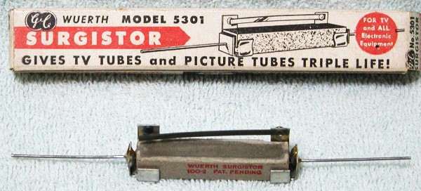
I have a couple of examples of a vintage device called a "TV Life-Saver", sold by a company called Wuerth. Basically, it's a 'wall-wart' which consists of a metal box with prongs on the back and an outlet on the bottom, with a Surgistor inside. You plugged the TV (wattage rating listed on the box was 100-240W, IIRC) into the box, the box into the wall, and it provided some sort of slow-start to the TV as it turned on. Guessing the device used in the W4-AM was a bit more sophisticated, but it's hard to say (apparently, seeing wisps of smoke emitting from inside the TV Life-Saver was a normal part of its operation! :eek::rolleyes:). I have yet to find a picture of a "TV Life-Saver", but here's a picture of the sort of Surgistor which is probably inside of it:
surgistor-wuerth.jpg
 
The earlier iteration of the Wuerth surgistor, possible the first unit the company produced. is identical to the unit in the Heathkit.

The later one used a cement-filled wire-wound resistor for heating.

As far as photos of the Tube Saver Model 100A, I am often astounded by the sheer number of photos of electronics gear I've collected. Here are some for your viewing enjoyment.

The photos show that the Tube Saver was a giant wire-wound resistor and a bi-metallic switch. The heat from the pilot-light bulb alone in that closed box would likely have been enough to trigger the bi-metallic switch.

Wuerth Tube-Saver 100A - Front.jpg

Wuerth Tube-Saver 100A - Rear.jpg

Wuerth Tube-Saver 100A - Inside - Straight.jpg

Wuerth Tube-Saver 100A - Inside - Angled.jpg
 
The surgistor pictured in post #1 appears to be the device in Patent Number 2,914,637, filed January 1956.
https://patents.google.com/patent/US2914637

Referring to Figs. 1 and 2, a high-resistance, heat-producing element is preferably embedded in a rigid, elongated refractory body 11, which will become sulficiently heated by the heating of the resistance 10 to cause actuation of the thermomotive member. . . .

The thermomotive member 14 is preferably bimetal and it may extend, as shown, around the end of the refractory body in portions 15 and 16. . . .

When the refractory body is heated by a flow of current through the resistance element 10, the bimetal thermomotive member 14 is readily heated and, because of its thermal properties, tends to flex upward into the position shown in dotted lines, eventually causing contacts 17 and 18 to close. At this point, current flows through the path 15, 14, 17, 18, 19 instead of through resistance 10. . . .

The thermomotive member 14 must be selected from a variety of materials and of such dimensions that the current flowing through it will produce suflicient heating to keep it flexed into close contact position.

US2914637-drawings-page-1.png
 
Nice work in digging out the patents, RTally.

Wuerth's patents should have been denied as considerable prior art existed and the refinement is void for obviousness to anyone with a modicum of skill in the field. They add absolutely nothing new, beyond some trivial and obvious packaging.

Time-delay relays which relied upon the heating of bi-metallic strips to close a contact were well-known and well-used for this specific purpose, going back to the early 1930s. The common name for such devices was "thermostatic relay". It was common prior art in the 1920's—at least 25 years prior to the filing date—to use thermostatic relays to prevent B+ from reaching a transmitting tube before its filament was fully hot, because the transmitting tube would otherwise be destroyed. Similarly, thermostatic relays were used in the late 1930s to protect CRTs from being destroyed by operating the beam before the filament was hot.

Hardly an original idea.

Further proof that then, as now, one might sneak worthless patents past examiners who were woefully ignorant or significantly overworked, or both.
 
Working as a patent attorney, I enjoy researching items like this because I don't have to. :naughty:

Using today's patent criteria, these inventions might not be patentable. But considering how inventions and patents used to be viewed, these inventions were properly patented. The patent claims are narrow and specific. The patents reference the B+ delay circuits as prior art, but those patents were also narrowly focused and gave no hint that ramping up the filament temperature was desirable. Remember, back in those days, everything was new and most inventions were discovered by experimenting to see what happened. Having cut my teeth with tubes in the early 60s, I think it obvious only in hindsight.

Back in the day, patents narrowly described only a single invention that was generally implemented in a single product. Not today. Now we write patent applications with broad descriptions that cover every possible variation and configuration. Even though today's patent claims are typically narrow in scope, the disclosure is so broad that most related inventions are rendered unpatentable.
 
Working as a patent attorney, I enjoy researching items like this because I don't have to. :naughty:

Ahhh, of course, the busman's holiday. After I left research I did a fair bit of competitive analysis and research for attorneys, and wrote memos and briefs. (Most hired paralegals and researchers do to the actual work.) It's a lot nicer to perform research when no deadline exists and nobody will be upset because the giant killer either was found or couldn't be found.

Using today's patent criteria, these inventions might not be patentable. But considering how inventions and patents used to be viewed, these inventions were properly patented. The patent claims are narrow and specific. The patents reference the B+ delay circuits as prior art, but those patents were also narrowly focused and gave no hint that ramping up the filament temperature was desirable.

Yeah, ok, sure, but I have patents and papers going back to the 1920s and 1930s on this idea. Weurth didn't cite that prior art and neither did the examiner. Probably because it was hard to find those papers in dozens of different hobbyist and trade magazines, or look up the dozen patents in the records. Barbie says, "Research is Hard!" Particularly when it's all on paper and the Memex is fifty years away.

Over the past few years I've been writing up a monograph on the history of the idea, so I have an unfair research advantage here. :)

Examiners in those days were often not as knowledgeable as they should have been. One of the biggest botches was the transistor patents. In retrospect we can see these never should have been granted. Between Losev, Lilienfeld, and Heil it had all been published or patented, and Bardeen and Brattain knew of that work. So did Shockley, who had replicated Lilienfeld's work, subsequently lied about it, and was caught. Plus the crucial contributions of Gibney, Ohl, and Scaff were omitted, which makes the patent vulnerable as the purported inventors weren't. We now have their recollections in the record about who did what, and, most important of all, who didn't do what. In consequence the attorney should have been disbarred because he very likely knew of the shenanigans. Anyway, the first round of patents was denied, and they had to scramble to get something issued. Such a mess. But that was Shockley. Man couldn't tell the truth about anything. As the mafia saying goes, a fish rots from the head down.

Anyway, in hindsight we can see how Shockley was a patent troll, perjurer, and plagiarist. It was not so clear at the time.

Back in the day, patents narrowly described only a single invention that was generally implemented in a single product. Not today. Now we write patent applications with broad descriptions that cover every possible variation and configuration. Even though today's patent claims are typically narrow in scope, the disclosure is so broad that most related inventions are rendered unpatentable.

Sure, I am well familiar with being as broad as possible. (I hold a few US and European patents, which I wrote, and I've been involved with other applications.)

The other trick back in the day was to delay patents as long as possible, constantly tinkering with them as technology caught up to a bogus patent. That was how Jerome Lemelson made his money: as a patent troll. Here's one example:
 
The earlier iteration of the Wuerth surgistor, possible the first unit the company produced. is identical to the unit in the Heathkit.

The later one used a cement-filled wire-wound resistor for heating.

As far as photos of the Tube Saver Model 100A, I am often astounded by the sheer number of photos of electronics gear I've collected. Here are some for your viewing enjoyment.

The photos show that the Tube Saver was a giant wire-wound resistor and a bi-metallic switch. The heat from the pilot-light bulb alone in that closed box would likely have been enough to trigger the bi-metallic switch.
Very interesting! Looks a lot more complicated than the "TV Life-Saver", which is in a smaller box and doesn't have a pilot lamp. Guessing the "Tube Saver" is from the mid-late '50s, while the "TV Life-Saver" probably hit the market in the early-mid '60s, and is based on the sort of Surgistor I posted a pic of above. Next time I come across one of my TV Life-Savers, I'll take a few pictures of it and its innards.
-Adam
 
Very interesting! Looks a lot more complicated than the "TV Life-Saver", which is in a smaller box and doesn't have a pilot lamp. Guessing the "Tube Saver" is from the mid-late '50s, while the "TV Life-Saver" probably hit the market in the early-mid '60s, and is based on the sort of Surgistor I posted a pic of above. Next time I come across one of my TV Life-Savers, I'll take a few pictures of it and its innards.

That will be interesting to compare the photos. Particularly to see if the bi-metallic switch at all changed in construction.

Not that many ways to build a thermostatic switch, particularly one heated by a giant resistor.

I was over at a friends fixing a 1980s mechanical thermostat (landlords generally refuse to invest in new technology or to fix anything) and it looks pretty much the same as the units from the 1950s. Cleaned and polished the contacts (which lack any sort of arc suppressor and are consequently pitted, even though it's low voltage) and it was good to go.

Edit: fixed typo.
 
Last edited:
Back
Top Bottom