0A2 regulator tubes

currituckco

Super Member
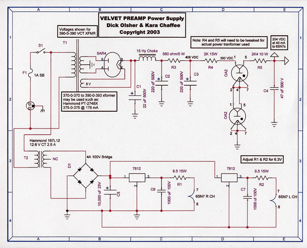
Anyone have any experience with these? I'm building a preamp (see thread: http://www.audiokarma.org/forums/showthread.php?t=155393) that uses a pair of these in parallel and I haven't been able to get them to light up even. They light up in my tester but not in the circuit.

Does anyone know what input voltage they require to light up? The schematic puts 300VDC on the input, but that also confuses me because 300vdc is the supposed output as well - don't regulator often need a higher supply voltage than their output will be? Also I found this:

http://members.aol.com/sbench/reg5.html

Their parallel example is an 0A2 and an 0B2, producing 265v regulated. Their supply voltage I think is much higher, if I'm doing my Ohm's law right:

"Since the power source produces about 490 volts when loaded with 20 or so mA, I'll use a 10k resistor to drop the voltage to the 2 series VR tubes, passing slightly more than 20mA thru the tubes."

I took this to mean .020A x 10kR = 200v, which would be the voltage drop on the resistor...so 290v supply voltage. Is this correct?

I can't figure out what's wrong in my circuit...Schematic in the other thread and details of my problem...

I guess my question here is, what does it take to get these things to light up? Is it a certain input voltage? Is it something else?
 
Register to hide this ad
hey-Hey!!!,
There are a few things to consider. The tubes need a certain amount of overvoltage to light up or 'strike', usually about 25% or so, unless it is hindered by age and or darkness.

Second the dropping resistor from the unregulated supply has to approximate a current source, in order that a small change in voltage does not make a large change in shunted current. One description/recomendation suggested 2x the regulated voltage for this supply.

Third pertains to the regulator performance; the regulator tubes and the dropping resistor form a voltage divider( for AC ). The larger the dropping resistance the greater the ripple reduction. A current regulator can be applied here usefully; an impedance of several or tens of MOhms compared to the hundered or so per regulator tube should show an obvious conclusion v. the regulation over a few thousand Ohms for the usual dropping resistance the 2x parameter would deliver.
cheers,
Douglas

your math suggests a 465V unregulated supply would be required.
 
VR tubes can't be connected in parallel - only one will fire. If you mean series, one trick to reduce firing voltage is to put a high-value resistor across one (say 470K)
 
your math suggests a 465V unregulated supply would be required.

hi guys, thanks for the responses.

I'm a little confused - is there a situation in which the values on the schematic should work? what am i missing here? is the circuit in the schematic unviable as written?

thanks Tom, yes I meant to say series...sadly i won't have time to tinker again for a while but i'd like to gain all the theoretical insight i can before i get back to it. since the schematic shows 400v BEFORE the series resistor, how is it possible that it worked?

so in that example of an 0A2 and an 0B2 (which regulated less voltage) producing 265v and needing a 465 supply, how much should two 0A2's in series need to produce 300v regulated? certainly more than the design I was building supplies... I'm utterly confused!
 
According to data sheets I read the "strike" level for the 0A2 as 155 V. If the voltage at the feeding resistor is 400V unloaded there is no reason why both tubes shouldn't fire, save perhaps a wiring error somewhere among them. If the unloaded supply voltage is less than 310V then you may have a problem.
 
According to data sheets I read the "strike" level for the 0A2 as 155 V. If the voltage at the feeding resistor is 400V unloaded there is no reason why both tubes shouldn't fire, save perhaps a wiring error somewhere among them. If the unloaded supply voltage is less than 310V then you may have a problem.

The 0A2 is a 150V regulator, that it would strike so near its operational window seems a bit suprising. I've run series strings of 0D3's to deliver 300V, and a 100k resistor across the upper one will apply voltage at a slight current to the lower one so as to avoid a 370V strike.

Now PS design can work with you here. Feeding the design from a choke input filter will allow significant voltage rise if the VR tubes don't light and draw current.
cheers,
Douglas
 
According to data sheets I read the "strike" level for the 0A2 as 155 V. If the voltage at the feeding resistor is 400V unloaded there is no reason why both tubes shouldn't fire, save perhaps a wiring error somewhere among them. If the unloaded supply voltage is less than 310V then you may have a problem.

I'll have to look for some sort of wiring error - I checked and rechecked but for the life of me couldn't find a problem...Unfortunately I hop on a plane in about 5 hours so the project will be on hold for 2 months...but rest assured I will get this guy rolling...even if I can't get the regulators to work, I can just dial the resistors to get the proper B+, there's already quite a bit of smoothing capacitance (22-220-220-47) as well as a 16H choke...it should be pretty stable and quiet, no, even without regulation?
 
Now PS design can work with you here. Feeding the design from a choke input filter will allow significant voltage rise if the VR tubes don't light and draw current.

I'm not sure what you mean here - is allowing voltage rise in this case a good thing? I'd love a further elaboration if you have a chance. Thanks!
 
I'm not electronically inclined, nor do I read schematics well. But I've included the schematic diagram for my BEZ Model Q4B SRPP linestage preamp in hopes that maybe it can help you shed some light on your regulator tube situation.

My preamp uses OC3 and OD3 gas regulators...maybe there's a circuit snafoo you're not aware of or maybe missed somewhere that's keeping yours from not operating. I'm not about to tell you anything that you don't already know 'cause I don't know nuthin' about how my pre's circuit works. I'm just hoping that this schematic may show you something...anything that may help you out.

Good luck...
 

Attachments

  • schematic Q4B.JPG
    schematic Q4B.JPG
    62.9 KB · Views: 168
I'm not sure what you mean here - is allowing voltage rise in this case a good thing? I'd love a further elaboration if you have a chance. Thanks!

hey-Hey!!!,
First some background. Choke input filter behaviour, at current past the critical point, voltage output is ~.9x the rms input AC voltage. Below this current it increases towards root2 x rms input voltage. On VR tubes, without getting them to strike, there is no current flow.

Sooooo, if we assume the load( and not current passing through the VR tube) is small compared to critical current the unregulated voltage will rise above .9x rms until the regulators strike and increase current draw.

Now if we employ a current regulator instead of a resistor in order to avoid super-high B+, or unregulated B+ only slightly above regulated to avoid heat in the CCS we'd worry about striking the VR tubes. So until they strike, unregulated B+ goes a bit higher until current demand increases to design levels.
cheers,
Douglas
 
Interesting. So you think that the current is below it's critical point (the minimum point we want for this design) and this causes a voltage rise - however, the voltages I measured were much lower than the design states past the series resistor before the regulators. I'm definitely not seeing B+ going higher, unless you are talking about the rectified DC voltage before the resistor/regulator section. Is that what you mean? When you talk of the super high B+, where would that be measured? Across the 2k4 resistor after the regulators? I was getting uncharacteristically LOW readings there - around 75v where i should be getting 204 if everything was working properly. Thanks again for working with me on this, I'm excited to get in deeper and learn more about design concepts rather than just paint-by-numbers kits and replacing caps with exact equivalents....
 
Hello, I'm finally home and hoping to sort out the power supply in this preamp. Reading back on this thread, I'm still a bit confused as to what I should do.

First of all, the schematic for the preamp the person posted above has the regulators wired differently than in my preamp - check the schematic:

BVPS2.jpg


I'm considering doing away with the regulators entirely since I'm not sure how to make them work, and putting in a dividing network to get me the voltages I need. Unless anyone here can give me an idea - possibly in the form of a specific instruction. Are there any specific measurements I should take first? Should I measure the current at the resistor before the regulators? What would that information tell me?

The schematic from jt1stcav uses different regulators that have different pinouts and wirings. Basically, pins 3 and 7 of the 0C3 and 0D3 are used to ensure that the circuit gets no DC unless both regulator tubes are installed. The 0A2 doesn't have dedicated pins for that for multiple series regulator tubes, just ones so that if a single regulator tube is used, and it is not installed - the circuit sees no DC (pins 1 & 5).

One thing that may be happening that is causing trouble is - if the 6SN7s are warming up quickly and drawing power supply current, lowing the voltage across the regulators before they have a chance to fire. I used PSUDII to find out that, when the 6SN7s are drawing 40mA, the voltage across the two regulator tubes is about 380VDC, and the datasheets spec a minimum supply of 185V each, maybe too borderline for it work well with all 0A2s. What may work is a 10-15 second delay until the 6SN7 heaters are turned on - so the GZ34 has time to turn on and deliver enough DC to the VR tubes to strike. You could try this by hand with a toggle switch first (on the filament tx) to see if it'll work.

One thing I don't like about that schematic is the early stages - during normal operation the first cap sees 480VDC +/- 10Vripple (and that is with the 370-0-370 V TX) - pretty borderline for a 500VDC cap. Similar PS performance could be had with fewer stages and a lower voltage power TX.
 
This is my take on it, from a very limited point of view.

At C3, we see that the B+ voltage is listed at 408VDC. Then there is R4, (2K@15W), then the regulators in question with 300VDC clearly marked. I believe that if the circuit was working properly, you would indeed measure 300VDC at that point. What happens is that you need more than 300VDC to get the VR tubes to strike, and for their continued operation. But, while they are operating, they consume this "overvoltage" and you get a steady 300VDC at that point.

I would:

- measure at C3 to make sure you get 400VDC+

- measure at the regulator position to see that you get more than 300VDC

- measure the resistance of R4 to make sure that it's within tolerances

- maybe try a smaller resistor value at R4 if you have the right voltage at C3 and not enough at the regulators

- try different regulator tubes / sockets

In the schematic is seems there is some leeway in the PT HV winding allowed. Perhaps they use the VR tubes to make sure that the supply gives the same B+ despite these differences.

Good luck!
 
That is a funky supply: If I had a 375-0-375 TX and I wanted lower voltage, I'd use a choke input power supply. Bricktop is right, why would you boost it to almost 500V with a cap input supply, then knock it down to half that? I might be tempted to get the original supply working if I could, just to solve the riddle, but I would not hesitate to deviate if you find a more elegant solution.
 
I have a 390-0-390 xformer, per the design. Here are my measurements, as I made them 2 months ago (I haven't actually sparked the guy since I've been home):

At the C1 - 490v
At C2 - 445v
At C3 - 400v
R4 is a 2k/13W - where I'm supposed to be getting 300v I was only getting 250v. I tried to drop the resistance of the 2k/13W by paralleling it with another 2k/13W - this only brought up the voltage after it to about 280V, and the 0A2's still didn't light up.

I paralleled a 2k4/10w along with the two 2k/13w giving a total resistance of about 700ohms...here are the results:

First cap (C1): 496
After choke (C2): 442
After R3 (C3): 390
After paralleled resistors (at 0A2): 325
---the 0A2's still did nothing - didn't light up, didn't change the voltage at all
After 2k4R (R5): 113

Should I just try pulling the 6SN7s and see what happens? Or disconnecting the filament trans?
 
Hmm, something seems funny at the load. Make sure the 6sn7s have the proper plate and cathode resistances. That 113V at the load tells me that something may be drawing a lot of current. This may be keeping the voltage across the VR tubes from getting high enough to strike. It's drawing (325-113)/2400 = 88mA right now....:scratch2:
 
Yowza! So it would be a problem with the circuit in the signal section. Will look there and report back later today.
 
AHA!

It appears I switched some of the 6SN7 wiring - I thought the plates were 1 and 4 and the grids were 2 and 5, but it's vice versa!

I wonder if I toasted those 6SN7s by putting the plate voltage on the grids? Thankfully I was using low testing spares...

Time to sling some solder and see what happens...Perhaps I should also put R4 in the power supply back to where it was...
 
Back
Top Bottom