

-
Feeling lucky? Check out the AK 24th Anniversary Giveaway thread and join in the fun!
You are using an out of date browser. It may not display this or other websites correctly.
You should upgrade or use an alternative browser.
You should upgrade or use an alternative browser.
MX-1000 Sub Circuit Board Changes
- Thread starter sonavor
- Start date
So, do I further apply the updates (comments/ observation from #7-9) to my boards which already have the soldered together 12 mH, 330 ohm, 1uf capacitors to the one 2.7k resistor?
Does the serial number of your unit start with E01..?
That is a factory modification to the first production boards. The later boards had incorporated tha same changes neatly on the boards. On the schematic I believe the components are reflected in the schematic. Should not need to modify either configuration unless the components are bad.
I am curious of the serial number. Have been tracking these.That is a factory modification to the first production boards. The later boards had incorporated tha same changes neatly on the boards. On the schematic I believe the components are reflected in the schematic. Should not need to modify either configuration unless the components are bad.
E02. Ends with SU. 1689 sandwiched in between. Yum! 
Okay. Will replace all components on the updated mod. for reliability.
Current values: inductor 12.7 mH, 2711 ohm resistor, 331.4 resistor, 960 nF cap/ Esr 2.9.
Using metal film of same wattage on resistors and poly metal film for cap.
All caps, resistors, trannies, testing good on L ch. so far. Will keep most.
2 Diodes 5kf10b values don't jive- Ir 78 na, uf 483 mv, c=156pf/ Ir 87, uf 476, c=145pf. I'll look up data sheet.
Still working on the board. Writing down values on L ch to compare with R ch.
Issue: Protection light, no output. No apparently burnt -leaking components. No signs of missing traces. So far. Lol!
Love those radio hack desoldering irons!
Recommendations appreciated.
Last edited:
Should not need to modify either configuration unless the components are bad.
I second what Avionic said.
E02. Ends with SU. 1689 sandwiched in between
very interesting, thank you!
I have seen and worked on quite a few MX-1000's
Only one with E01...serial number. The revision components were missing all together
Two with E02...serial number. The revision components were on the boards already. I noted minor variation on the boards comparing to later E03..+ units.
The rest were all E03...and up.
This being said, I am assuming that the factory modes such as the modes done to your unit and Sonavor's unit, were done to early E02...units, with later E02...units having the boards updated.
on a post by Avionic dated 2011, suggested: "The MX-1000 also has a few HEXFRED's in there 5KF10B
Ultra-Fast recovery diodes TO-220 case style
http://www.mouser.com/ProductDetail...=sGAEpiMZZMtEwUVCuofpuJ8elz361Z6mbGXa912nyj0=
Note: Pin 1 on the 5KF10B is not connected electronically , so pin 1 needs to be nipped off of the MUR2020 before installation."
Pin one must be the pin on the left of 3. I'll go with these.

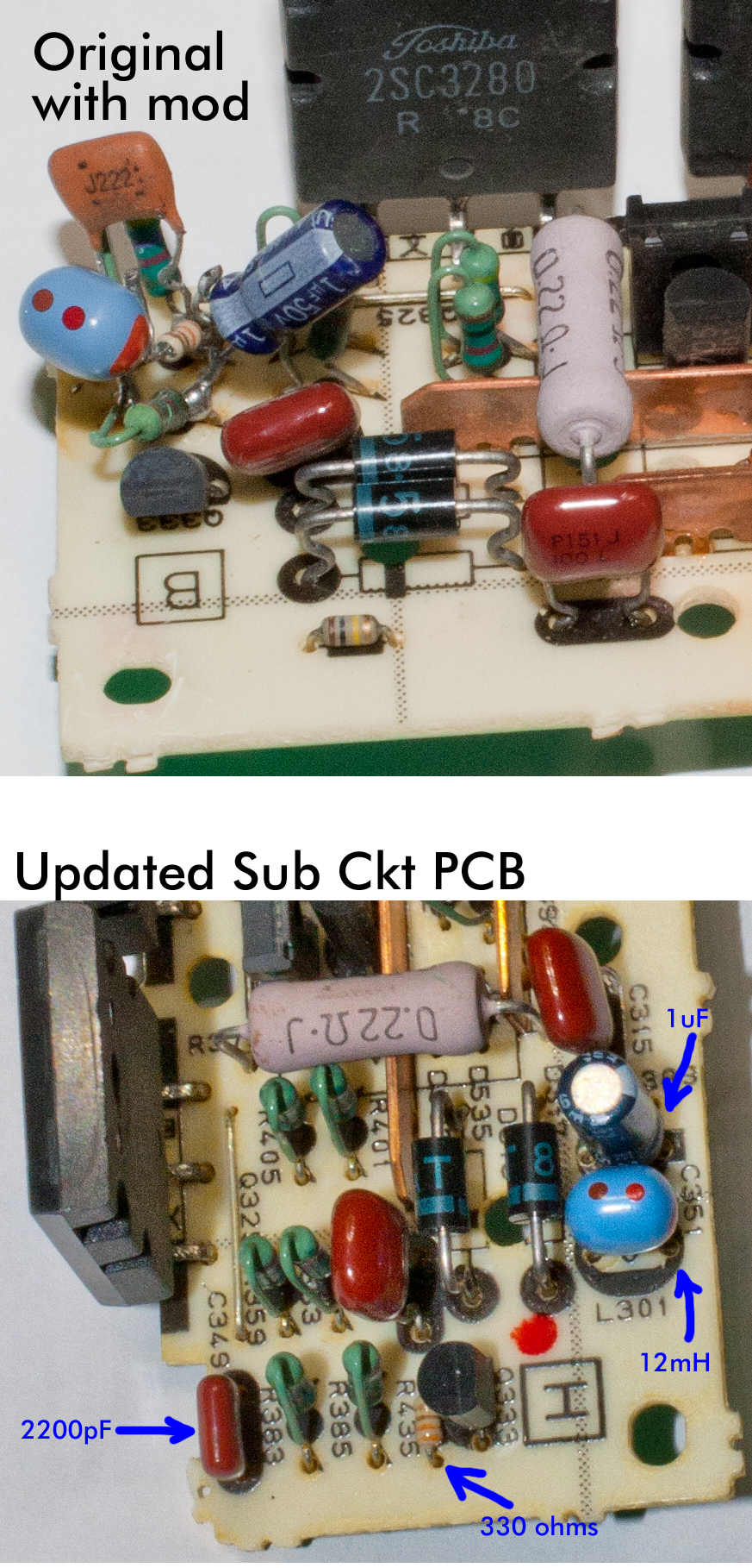
Here is a picture of the component side of the two versions of the left channel sub circuit board. The top picture shows the original board with the modification that added the four additional components. The bottom picture shows the updated version of the board with the four components in designated locations.
I'm currently updating the left channel sub circuit board modification on my board with new components. The schematic here is not in the same order as the original setup or pictures. The original setup and pictures here goes like this: one side of 2.7k resistor to 12mH inductor to 330 ohm resistor to negative side of the 1uf capacitor positive side of 1uf capacitor to other side of 2.7k resistor. The schematic displayed here goes like this: negative side of 1uf capacitor to 2.7k resistor, positive side of 1uf capacitor to 12mH inductor to 330 ohm resistor to other side of 2.7k ohm resistor. Which one is it?
Mika.T_FIN
Member
Does anyone have any pictures of this thread?
I have MX-1000 and left channel has mysterious oscillation...
I would be interested in what the updated connection does. Mainly what is the purpose of the L301 inductor
I have MX-1000 and left channel has mysterious oscillation...
I would be interested in what the updated connection does. Mainly what is the purpose of the L301 inductor