Sansui QR 4500

sKiZo

Hates received: 92644 43.20°N 85.50°W
PS ... I just edited this four year old post ... because I could! SUBSCRIBE, and you can do it too!!

IMHO ... One of the best looking receivers ever built.

qr4500-original.jpg


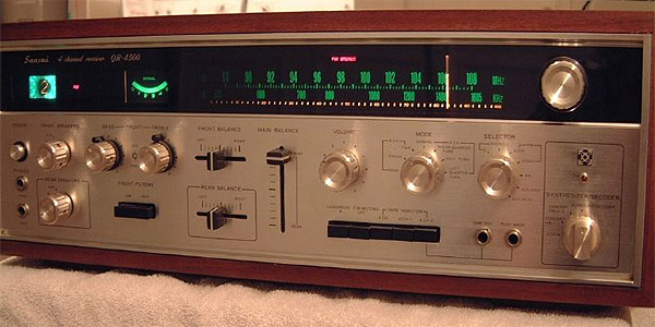
Granted, not one of the stronger amps - only rated at 27w x4 per channel - but keep in mind, these are old school watts, and better yet, old school SANSUI watts. Extremely conservative in their ratings. I've had several over the years and always liked the clean rich sound. Although the channel processing is considered primitive compared to the TOTL QRX quads (no SQ, CD04, Dolby), that can actually work FOR you when synthing from a stereo source. The I/O is just short of spectacular. There's really nothing you can't hook up to the thing, and the speaker selection is outstanding. Two sets of four, four sets of two, and you can run any two as well as reverse, twirl, and maybe even turn them upside down while you're at it. The pre out/amp in loop is indispensable for outboard processing.

qr4500-back.jpg


But I digress.

I'll be doing a rebuild on this one while I gather information (and the courage) to tackle a QRX9001. Something tells me I'll need the practice.

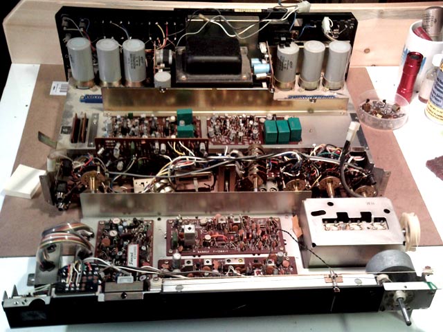
So here we are so far.

qr4500-rebuild-013.jpg


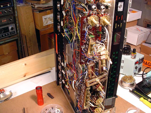
- Front panel removed.

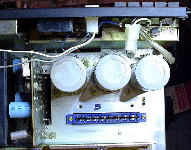
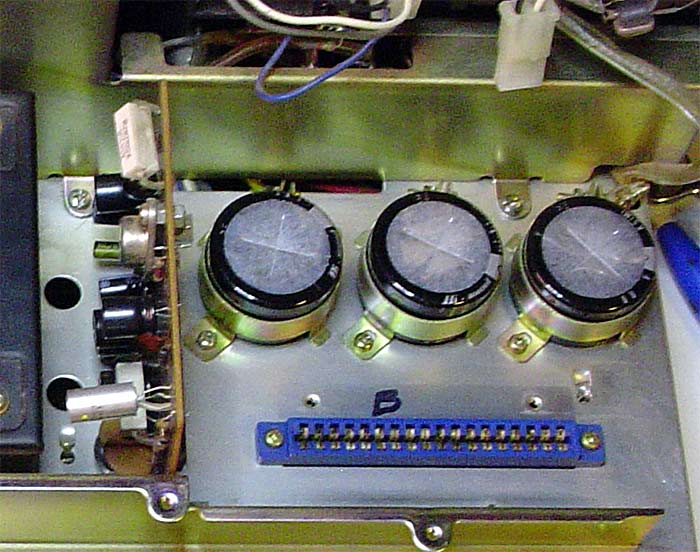
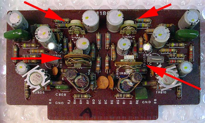
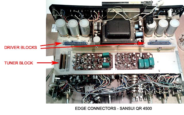
- Driver blocks (F1180E x2) removed. Those are slip in cards with edge connectors. Good just to get those out of the way and stashed in a safe place for now.

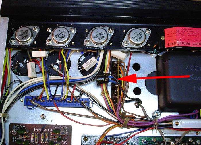
- Heat sink/power transistor assembly moved back to allow better access to power boards. Removing it entirely would require quite a bit of extra work you really don't have to do. That extra inch makes a big difference later on when you tackle the power boards. I <may> decide to remount the transistors with new insulators and heat sink compound as the old stuff wasn't all that good to begin with. Heat is the killer, so ... head it off at the pass.

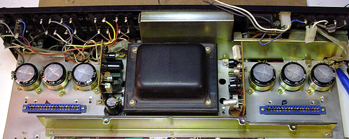
- Tuner section removed. This is a neat feature that should be mandatory on ALL receivers. Eleven screws, pop the main I/O connection, slip off the antenna leads, and the whole shebang lifts off. Don't have to mess with dial strings, and clears access to the lower tier of boards. The tuner section will remain untouched, other than general cleaning of the boards and connectors. Tuner alignment is best left to the professionals, as any change to the original components WILL require a full realignment. Unless you've got drift or other known issues, best to just leave it alone. A bit of Fader Lube to restore the original spin to the magic wheel, and some Pro Gold to restore all the contact surfaces should do it.

qr4500-rebuild-tuner.jpg


Some of the modular features on these things take a lot of the work out of it. 70s tech wasn't all bad.

qr4500-edge-connectors.jpg


One thing I will have to do is re-point all the solder connections on the light board. Those tend to go open or intermittent over time due to all the heating cycles. I'll also replace all the fuse lights while I'm at it. The old ones work, but ... famous last words there.

Not bad for a days work.
 
Last edited:
Register to hide this ad
Capacitor Selection

Did my cap selection for this one based on some feedback I got in the following thread:

http://www.audiokarma.org/forums/showthread.php?t=400828

... made a couple minor tweaks to the list, placed an order with Mouser, and am waiting for the guys in the little brown trucks <beep beep>. Upgraded to audio grade Nichicon where available, and then Panasonic FMs. Was able to get exact voltage matches on all the electrolytics. I also wasn't happy with what I'd found earlier for the main power caps due to the size. Quite a bit smaller than the originals - 25mm vice 35mm - and they were general purpose to boot. BIG difference in size that would require some serious mounting adjustments. I was also planning to go with the 30% rule for the main power caps, which would put me somewhere in the 2700-2900µf range. Couldn't find a match that would work, so I "settled" for factory spec of 2200µf80v x6.

http://www.mouser.com/ProductDetail/Nichicon/LKS1K222MESC/?qs=ppWA7IX8Fw5csJJFra8cBg==

35mm diameter to match the original clamps. Outstanding! Also outstanding was the price. Yeowch. With just those, I've already doubled the money I've got into this thing. <G>

One recent discovery - you're MUCH better off just typing the cap you need into the search box rather than using the Mouser pick lists. By doing that, I found some Nichicon (audio grade!) snap ins that are an exact match for size. Just be sure to use the Mouser conventional description ...

EXAMPLE >> Nichicon 2200µf 80v

I'm toying with the idea of using the QR4500 as a test platform to settle the question (in my own mind anyway) of whether bypass caps make any difference in the ear of the beholder. This is a quality box and should be a good candidate. I've got two of them. Problem being ... one has already been rebuilt using somewhat different caps, and in order to do a valid comparison, I'd have to break that one open again and match it to this one - except for the additional bypass caps.

Of course, that all depends on whether all the other components are equal sonically and that the fine folks at Sui didn't slipstream any changes into the design. And that I don't develop an ear wax condition between switching boxes in the listening room. <G>
 
Last edited:
While yer obsessing over caps ... what about the resistors. New metal film resistors sound mighty fine in my Citation preamp! Just sayin...

Cheers,
Bob
 
You rat ...

Just when I thought I was ready to welcome the bird of paradise into my life, here you drop by with the chicken of depression in tow ...

:butt1:

* I'm playing around with smiley faces here. Hope I got the right one ...

I suppose it would depend on how bored I get, or how masochistic I'm feeling. Never really saw the sense in it unless you're talking really old carbon resistors that have a tendency to swell and go open over time. I do check for fusistors, and haven't noticed any of those in this box.

I expect I'll pass for now ...
 
Decoder tweaks

Anybody? I know there's a "holy grail" alignment that can make the QRX units sing. Anything out there for the old QRs?

For that matter, the service manual is sorely lacking in anything even remotely resembling service. It's got the procedures for adjusting current and output as well as tuner alignment, but absolutely nothing when it comes to the synth, modulator and tone blocks.
 
I enjoyed seeing your photos of the Sansui. I just aquired one a few weeks ago, a little rough. It had a broken fuse holder and no power cord. I tried every power I had like those and none fit. I guess I will have to solder in a power cord or make something work.

picture.php
 
:smoke:Its nice to see the receiver taken so far apart. If I didn't have so many projects I would follow your lead, and Thanks for
picture.php
the tips on ordering.
 
Missing power cord

Looks real clean - then again, the bottoms always do. We wanna see the top!

The breakaway cord was to allow swapping in whatever you needed wherever you happened to be without having to use an external adapter. Problem being, they had a way of getting away from you. Somewhere there's a whole mountain of old power cords - probably right next to the mountain of lost socks. Not sure where those things go to. Maybe somebody on the board has a spare. I've got a couple - and no, you can't have em,said the packrat in me. <G>

At least these are easy - compared to a lot of power cords. Here's a couple head scratchers in my collection:

powercords.jpg


A true audio restoration purist would make a wax mold of the socket, modify crimp on slip connectors for an exact fit to the posts, then make a replica connector from PlastiFix using archive photos of the original, molding that directly to the new cord. Goes without saying, they'd also look high and low for a RED cord to match the original. These are the same people who spend months looking for a bolt with the exact markings and specs for their '55 Corvette.

(There .. I probably just offended at least half the people on the board.)

Bah.

If it were me, I'd just lop off one end of a good flat wire extension cord and use that. Easy access to the original plug socket. Desolder the wires inside to the power connector, then remove the connector and make a simple plate to fill the hole. put a hole in the new plate big enough for a strain relief grommet, then solder the wires and you're done. Just make sure you attach the wide blade side of the plug to the white wire to keep the phasing correct.

All that of course assUmes access to some basic tools.

* Real important - do double check the current settings and make sure your power is set up for your locale. That BIG RED sticker is a clue how important that is.
 
Pioneer Quads

:smoke:You are correct the power cord is the easiest to remedy, I have several of the 2 hole plug power cords but none fit the Sansui. I like the idea of putting a plate and strain relief, I didn't think of that one. I also thought of taking a computer recessed power connector and fitting that into the receiver, to much work.

Depending on the piece of equipment I might spend some time to find the correct screw, color wire etc. I am also ok with repairing it *especially if no one will see it* anyway I can.

I try not to permanetly alter any vintage equipment, if you repair it with a different part and it works you can always look for the correct one if its worth it.

I have a 1969 Z28 Camaro in the garage, when I bought it in 1979 I cut up the dash where the radio was to put in guages. To repair that you have to replace the dash cluster. Oh well at least I didn't put flares on the rear quarters.

I will take some photo's of the top, the receiver was damaged on the rear corner and broke one of the fuse holders. I soldered in a replacement *not correct* but functional.
picture.php
 
JVC Quad Receiver

This JVC doesn't have a lot of power but I like it. You don't always need a huge amp. If I could only have one amp or reciever yes I would get a big one.

At work I have a small Pioneer vintage receiver that I rescued from the dumpster, its background music. Since I have many vintage receivers and amplifiers its nice to have a selection, like tools.

I don't just have one or two screwdrivers I have several just like stereos. I love to hear and feel the music but depending on the situation all the stereo equipment has its time and place.

This little JVC has dual power supplies and works very well, other that the cracked glass around the joystick its not bad condition. I just love how the joystick is engineered. I even bought a smaller version just for part, *the cracked glass*

Its nice to have spare equipment, I try to get at least 2 of everything, that way:yes: when you forgot how something is installed you can look or take parts from one to the other.
picture.php
 
The less alteration the better. The insert I mentioned would use the original mounting screws, so just stash the leftovers in a baggie and save them for a sunny day.

Ratshack has one that looks real close. Double check the size - you need a 3AG holder for an AGC fuse type.

http://www.radioshack.com/product/index.jsp?productId=2062231#

Another thing well worth mentioning - DO check the fuses that are currently installed. First thing I check when I say howdie to a "new" piece of equipment. Seems some folk figure anything that will fit should work, right? And really, what's the difference between a 2.5a fuse and a 25a anyway?

Ratshack also stocks the fuses you need in the correct ratings.

http://www.radioshack.com/product/index.jsp?productId=2102742
http://www.radioshack.com/product/index.jsp?productId=2102766

Not a bad idea to get a few extra if you're going to be wielding the golden screwdriver anywhere near it.
 
Sanusi QR-4500

You are correct about checking the fuses, I bought a Kenwood stack and I found a fuse wrapped in aluminum foil. I was not impressed when I saw that, I hoped the person that did that was just out of the size fuse.

I put in the correct fuse into the Kenwood KC-6060 oscilloscope and it turned on, and worked fine. I almost always inspect any new purchase, you have to see the condition and see what you have.

I will apply power to the Sansui tonite, I will make up a power cord with alligator when I go to work. I work at a hospital on the medical equipment *ventilators, surgical and monitoring equipment and
picture.php
almost anything else.
 
Qr-4500

Here is another photo of the top of the receiver. I have only cleaned the Sansui once so its still pretty dirty. Since my air compressor is broken at home I bring equipment to work. I work on it on my lunch and breaks, plenty of light and room at
picture.php
work. Not to mention all the intersting items I come across in my travels in the building. I will let you know if the Sansui comes to life briefly or smokes.
 
Baby steps ...

Finally a bit of progress. Had a few other projects up my sleeve, but the QR4500 is finally getting some attention.

- Cleaned the tuner section - not gonna touch that, as it works real well as is, and you need some fairly hefty resources to tweak one of those back into shape if you tear into it. Best left alone.

- Replaced all the panel lamps except for the pointer and 4 channel indicators which are doing fine. I went with 8v which are readily available and put out plenty light. Also retouched all the solder joints on the fuse lamp clips. Those dry and go intermittent over time on most any Sansui I ever ran across.

- Cleaned and lubed all the controls. Rather than leave all those pots and switches dangling, I did the F1363 tone board first. That hides behind the controls and needed to be done before reassembling the front panel.

Here's the original. There's enough slop in the wiring harness that I was able to prop it up high enough from the chassis to get good access to both sides. Wahoo!

f1363-tone-block-original.jpg


Resistors and gumdrops are all quality components (no carbon, thank the sui gods) so ain't gonna mess with those either. I've got a new solder station and am using Cardas quad eutetic solder which can be a bit finicky, but it dialed right in at about 630F. I did find it a lot easier to suck solder if I added a blob of new metal first to improve heat transfer. Then the pads cleaned right up spiffy. I did keep a close eye on the board markings and made sure they matched the original caps for polarity and such as Sansui does tend to get those wrong sometimes. No such problems on the tone board anyway. Here's the completed board back in place.

f1363-tone-block-done.jpg


This also allowed me to put the box back together enough to test my work so far. Lots easier than finishing it and THEN trying to track down a problem. Had a magic moment when I couldn't get the front channels to fart, then remembered I'd removed the PRE OUT/AMP IN bridge plugs ... dOH! Checks out ok now.

Not bad for a day's work ... NEXT!
 
Left power block done

Including the F1360 board. Once again, I was able to pull that up from the chassis just enough to get at the caps. Only two electrolytics on the board, but a bit hard to get to. Easier if you remove the large primary cap behind it, then the bracket screw to the chassis on the back, and the bracket screw to the board on the front. You can get extra slack on the wires by taking them out of the guide strap underneath, then wiggle it up and out a bit.

Also replaced the primaries on that side. Notice any difference?

f1360-power-left-bank-before.jpg


f1360-power-left-bank-done.jpg


I'm thinking a whole lot more air flow. <G>

Amazing the difference in size on the components from then to now. The shorties are exact matches to the original spec. I usually like to go with the 30% rule and increase the ùf value on the primaries, but nothing in that range was available. I was able to find the same diameter, so the OEM clamps work nicely. Not so lucky on the 100ùf 75v next to the transformer. Closest I could come was a 100ùf 100v. Close enough. I just gooped the bottom of the cap with rope caulk like they use on car windshields and jammed that into the OEM clamp. Works nice. Here's a closeup of that:

f1360-power-left-bank-clamp.jpg


Put it back together, fired it up - sounds good - no smoke.

NEXT!
 
Last edited:
And now the right power block is done

About three hours worth of work, and yet again, NO SMOKE! :thmbsp:

Before, including the F1362 board located to the right of the transformer viewed from the front of the chassis. That also had enough slack to do the work without having to mess with the wiring loom. You'll want to pay attention to the orientation of C014 and C017 as the board markings are ... ambiguous. My old trick of marking the side of all the caps facing me prior to removing them paid off as I was able to eyeball the correct polarity.

f1361-power-right-bank-before.jpg


After:

f1361-power-right-bank-done.jpg


Oh. Here's a view from the bottom.

power-right-bank-bottom.jpg


Don't forget the cap dangling off the bottom of the F1362 board. Looks like they worked themselves into a corner for C011. There's a spot for it printed and drilled on the board, but that's left empty. Surprised they didn't just add a bridge, but hey, that's why they call them inscrutable. :D

And the completed power bank:

power-bank-done.jpg


Once again, put it back together, fired it up, and it's good to go. Can't really calibrate it till I get the driver boards done, so I just ran it at low power enough to see if anything went <pOp> ... Nothing went <pOp>, so ...

NEXT!
 
psssst ... got it covered. That's kind of a Where's Waldo thing ... I know it's in here somewhere ...

bench-clutter.jpg


Ah. There it is!!

dimbulb-002.jpg


I guess I did forget to mention that.

Still not gonna run it up to full load until I get the driver boards done. That's where you do the current and output adjustments.

f1180e-driver-pots.jpg


No faults (as in smoke or exploding light bulbs) showing, so not much sense doing that until it's done. I did notice one thing that bothers me ... the paired drivers at the bottom center of each board ... well, for want of a more technical term ... look like crap. They work, but whatever passed for heat sink compound back then turned to some nasty looking sludge. Anyway, I did find out that the heat sink is just pressed tight to the cans. I was able to pry one off with some needle nose pliers and an Xacto knife. Here's one removed - the right side is loose, so it's a repeatable tweak.

f1180e-heatshield.jpg


Doesn't look like there's any real damage to the cans. I'll scrape and polish a bit (not too seriously - the transistors both look to be unobtanium grade), clean the copper heat sink and press them back with Arctic Silver. That should do wonders for heat transfer and keep them cozy for another 30 years.

<edit>

Looks like those paired transistors aren't as unobtanium as I thought. Did some more digging, and NTE cross-references them to a NTE129MCP matched pair. $18 will do both boards. Hmmmmmm ...
 
Last edited:
Film caps to replace small value electrolytics?

Having problems finding replacement caps for some of the low voltage electrolytics on the synthesizer boards.

1.5µF @15v
3.3µF @25v

Can I replace these with film caps in the same values? Those are rated at 250vdc, but are NOT polarized. Size shouldn't be a problem. I know substituting bi-polar isn't wise, but ... not sure about this. Only other issue I've seen is maybe additional crosstalk in the circuit due to the fact that they're not shielded. Heck ... if that's a problem, a quick wrap with foil duct tape should take care of that.

ECQ-EF%20SERIES%2015.8,15.9,16.0,16.5,16.8,17.0H,18.5L_sml.jpg


There's also a boatload of 1µF and other such small values that might benefit from the additional stability a film cap could bring.
 
Last edited:
Hey there,

I'm currently in the process of starting revisions on my own beautiful rescued QR-4500 and wondered where you ended up with your own restoration. Seems to have been cut off early, which would have been a shame.

Kind regards,

Bert
 
Back
Top Bottom