

You are using an out of date browser. It may not display this or other websites correctly.
You should upgrade or use an alternative browser.
You should upgrade or use an alternative browser.
Pioneer SX-1500TD Restoration
- Thread starter Willarado
- Start date
Bruno Primas
Well-Known Member
Be careful, I liked my 1500TD so much that I tracked down it's 72 wpc older brother, the 2500.

Bruno Primas
Well-Known Member
It works very well. One of the best things about it is that it has the 'FM Muting' adjustment on the FRONT of the receiver. I wish they ALL had that.
The auto-tuning is also used in AM mode, and the center-tuning meter is also used, so the light on it doesn't go out when you switch to AM.
The auto-tuning is also used in AM mode, and the center-tuning meter is also used, so the light on it doesn't go out when you switch to AM.


Bruno Primas
Well-Known Member
Yeah, not factory. Someone wanted to get inside the shield without taking the time to remove the cover properly.
Willarado
Active Member
Making progress. The power supply, main amp, phono/eq board, and mic amp board have been redone with new caps, transistors, diodes, and trimmers.
No resistors yet. I will see how things are working and jump into resistors if necessary. You guys suggested replacing resistors. Did you find that values were off, they were noisy, both?
The kit seller recommended not replacing the 2SC497driver transistors suggesting they don't typically go bad and replacing could bring bigger issues. Do you guys agree with that?
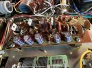
For those interested, working on the main amp will require removing it from the chassis and desoldering some wires. I chose to set a box under the board to raise it up so I didn't have to desolder all the wires. Also, note that when replacing the two 1000uf 50v caps with 2200uf, the negative lead should jump to both negative traces on the board. I just added some insulation and bent the lead over to touch the second trace per the photo.


No resistors yet. I will see how things are working and jump into resistors if necessary. You guys suggested replacing resistors. Did you find that values were off, they were noisy, both?
The kit seller recommended not replacing the 2SC497driver transistors suggesting they don't typically go bad and replacing could bring bigger issues. Do you guys agree with that?
For those interested, working on the main amp will require removing it from the chassis and desoldering some wires. I chose to set a box under the board to raise it up so I didn't have to desolder all the wires. Also, note that when replacing the two 1000uf 50v caps with 2200uf, the negative lead should jump to both negative traces on the board. I just added some insulation and bent the lead over to touch the second trace per the photo.
Attachments

Last edited:

Bruno Primas
Well-Known Member
Make sure your microphone volume is turned down all of the way. If up, it will add noise to your signal chain. Just a thought.
When running correctly, in 'aux' mode, you should have almost no noise with no input and volume turned all of the way up.
When running correctly, in 'aux' mode, you should have almost no noise with no input and volume turned all of the way up.
Bruno Primas
Well-Known Member
I believe I used the KSC2690AYS to replace mine. I think they are now obsolete so I've read the BD139 would be a suitable replacement for the 2SC497.
Bruno Primas
Well-Known Member
Is it quiet in 'aux'? Phono will always have some noise with no signal. It'll definitely be less with new transistors.
Bruno Primas
Well-Known Member
BTW, the amp board has 2SA497 AND 2SC497. The 2SA497 can be replaced with the BD140.
Bruno Primas
Well-Known Member
The 1220 and 2690 are now obsolete. The BD139/140 are the same design as them. The 2383 and 1013 are smaller.
Last edited:
Willarado
Active Member
Ok, all boards are recapped and mostly re-transitored. I still plan on replacing the main amp driver transistors. Hopefully, that will take care of the hiss/noise floor issue.
The left channel is still out on the FM tuner, right channel sounds good. Where would be a good place to start to track down this issue? The hacked FM front end W11-028 is certainly suspect, but I have no idea how to trouble-shoot that. It looks like the FM signal isn't split to left and right channels until the MPX unit. Is that correct? @john stumpf
The left channel is still out on the FM tuner, right channel sounds good. Where would be a good place to start to track down this issue? The hacked FM front end W11-028 is certainly suspect, but I have no idea how to trouble-shoot that. It looks like the FM signal isn't split to left and right channels until the MPX unit. Is that correct? @john stumpf
Last edited:
Willarado
Active Member
I finally replaced all the driver transistors last night. I set the bias to 10mv on both channels. I was able to adjust DC balance on the left channel to 72v/36v. However, when I went to set DC on the right channel I got 72v on Q11 but only 3.7v on Q12. I have triple-checked the installation/pinout on the new transistors. I am at a loss here since the channel was working previously. The only thing I can think of is that maybe one of the transistors I put in is faulty. I may put the old ones back in to check. Any other thoughts here would be appreciated.
