• The move to the new server is done. There are some software and database maintenance updates in process. This has us passing the hat around to help out. We appreciate any donations. Seriously, even a dollar helps. The payment page may be found here - https://www.audiokarma.org/support.html

Ultimate AM Atenna

Register to hide this ad
BTW, this is my actual antenna:

attachment.php


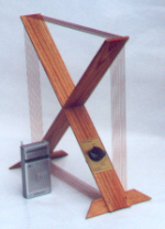
The photo in that thread is my Ultimate AM Antenna. The connector is a common two terminal barrier strip. There is ordinary 300-ohm twin lead going to the AM and Ground terminals on the tuner. This photo is from the assembly instructions:

attachment.php
 

Attachments

  • Ult Ant Connection.JPG
    Ult Ant Connection.JPG
    83.3 KB · Views: 666
Thank you much Paul for posting the picture. How do you have 2 prongs coming out from the base. Is this from both ends of the red wires (start and end) or you just wire one end in series to both connection at the base.
 
In the black terminal strip where the antenna twin lead is connected there are metal jumpers (which I sketched in blue).

The red loop wire goes from one of those screws, through a hole to the underside of the wood base.

From there the wire goes over and up through a hole by the support upright. It makes four turns around the supports, and then back down through the hole, over to the terminal and is connected to the other screw.

attachment.php


This antenna forms a 4-turn loop which is connected electrically from the receiver's AM terminal to the receiver's Ground terminal.
 

Attachments

  • Ult Ant Connection 2.jpg
    Ult Ant Connection 2.jpg
    45 KB · Views: 584
Remember, this is a loop antenna. Both ends of the loop must be connected to your receiver or tuner. It does not matter which end goes to which, but one end of the loop connects to the AM terminal of your receiver, the other end connects to the Ground terminal.

Loop antennas do not pick up like other antennas. The AM wavelengths are very long. A Quarter Wave antenna for 1000 khz would be 82 YARDS. A Quarter Wave for 540 khz would be about 150 yards... 1 1/2 football fields longs. A Quarter Wave for 1600 khz would be about 50 yards. So much for a "longwire" antenna for AM.

A loop picks up by magnetic induction of this very long wave, just as a tape recorder deck picks up the magnetic waves on the tape, or a phono cartridge's coils pick up the moving vibrating field created by the magnetized end of the stylus. And that loop needs to be complete. Disconnect the ground end from the receiver and the loop antenna will not work.

These very long waves broadcast more through the earth than the atmosphere. You can even listen with this antenna in your basement. Or so I've been told by friends elsewhere in the country. We don't have basements down here.

This loop is very simple, and could be said to be an "untuned loop", but it is really tuned by its size and number of turns of wire. If you were to make it larger you would have to change the number of turns on the form. There are other loops that tune with a variable capacitor, and can be fine tuned to give even better reception.

But this is the Ultimate in KISS... "Keep It Simple, Stupid!" Don't alter it. Make it as the Carver plans state. Make sure you use brass, not steel hardware. The "shoulder hooks" on the ends of the arms must be brass, and the screw, washers, and nut holding the cross together must also be brass. Only non-inductive hardware.

From the Louisiana gulf coast, at night, I have picked up stations as far away as WSB in Atlanta, GA, KHOU in Houston, WOAI in San Antonio, KMOX in St. Louis, MO, and most nights I can pick up WLS in Chicago.

And this antenna is directional. Do try rotating it for best results. I can get definite nulls and peaks.
 
So does the ground go to where the turntable ground connection is or is there a separate am ground connection?
 
For most tuners/receivers, there is usually a Ground terminal next to the AM terminal. Then beside that are two 300-ohm terminals. 75-ohm (shielded cable) is usually connected to the Ground terminal (shield to ground) and the 300 ohm terminal next to it (for the center conductor of the cable).

That Ground terminal is also chassis ground. The same with the chassis grount terminal for the turntable. Both are chassis ground on every receiver I have seen.

This is a typical setup:

attachment.php


BTW, with my Onkyo TX-866 receiver (in my bedroom system) and Ultimate Loop last night I listened to WLS 890 AM in Chicago. That is 970 miles from here. Almost no noise, very clear. The signal meter was pegged at 5. Sounded like a local station. Not bad for a few pieces of wood, a few bits of brass hardware, and a few loops of 22 ga hookup wire. :D
 
I built one of these tonight, but I could only find 20guage wire, not 22.Deso it matter if the two wires coming off are different lenghts, or should I trim one back so that they are equal? Also, my radio (a Zenith 5R680X here's a link to information about it http://www.nostalgiaair.org/Resources/989/M0024989.htm) only has two unmarked screws for antenna connections. I have one end of the loop on one screw and the other end on the other screw. The connections seem to go to some type of internal antenna that is a bunch of unshielded wire wrapped around in a rectangle, which then goes into the tuner section of the radio. I think I get better reception with it, but I'm in my basement and this radio was just started up for the first time in years, so it probably needs it's contacts to be cleaned or something.

What should I change on the antenna if I did it wrong, and what should I do to the radio to bring it up to snuff? Thanks.
 
Looking at the schematic, it appears your radio has a loop antenna already, and the two external terminals are for adding a "longwire" or other external AM antenna and ground. You may not get much more from adding the "Ultimate AM Antenna" to that setup as you would in adding it to a regular stereo tuner or receiver.

Looking at the schematic, it appears there is already a loop, (down by the lower left corner by the "John F. Rider" signature). The actual internal loop antenna has 2.5 ohms written by it. The smaller coil, marked 60 ohms and the actual connection to the two external terminals, is a "tickler coil" to bring an external signal to the radio's internal loop. The "A" terminal would go to the external antenna, and the other terminal to ground. I don't think this loop will do you much good, but you can try. Perhaps if you can go in and make connection (look at the schematic) where the internal loop connects, disconnecting the internal loop.

Your radio probably needs quite a bit of work, alignment, etc. Should be an interesting project!

----

In case any of you guys are interested, this is where this simple loop originated:

http://members.cox.net/rwagoner/columns/am_antenna.html

Carver Corporation of Lynnwood, Washington once made the ultimate AM Stereo/FM Stereo tuner, the Carver TX-11b. The performance of this tuner was nothing short of spectacular on FM; the AM side was even more impressive, as it was designed to have an audio bandwidth of 20 Hz - 15 KHz -- the same as broadcast FM!

In order to receive clear AM Stereo signals -- on the TX-11b or any other AM radio, however, you have to have a good antenna. So Carver gave a plan for making what they called "The Ultimate AM Antenna."


I purchased two of mine as kits from a fellow who kits them up and sells them on that famous auction site. Others I have built from scratch.

Right now I am building one of these. Will let you know how it works.

http://www.mtmscientific.com/loop.html

Loop1.jpg


It's a tuned loop. I purchased the plans with tuning capacitor for $20.

I'm adding a pickup coil to directly connect to my tuner.
 
Thanks Paul. After I read your post I went down and unhooked the antenna from the back to see how the reception was. The volume was significantly lowered, but the clarity remained the same. I think all fo the noise must be something inside it, probably one of the things that you mentioned, but I have no idea how to fix those. Is there a site anywhere that might help tell me what work to do and explain it a little? Thanks.
 
Ferrite Rod

I've never had a whole lot of success with relatively small passive loops such as these myself. Gain is pretty modest. On a really good radio with a good-size ferrite rod antenna (Superadio, etc.) you may not notice any improvement at all. Most smaller loops would greatly benefit from a preamplifier (active design). Problem is this often increases noise pickup from electronic sources around the house.

Long or random wires aren't bad at all when it comes to picking up the AM band: even if they are much shorter than 1/4 wavelength on broadcast band, they can usually receive AM broadcasts very well, with PLENTY of gain. They can, if properly designed, (with feedline shielded), and installed outdoors and away from electronic interference, be very quiet, especially when impedance-matched to coax and shunt-grounded at the antenna/coax connection with a proper transformer (9:1, 10:1). The main problem is that most long wire antennas are fixed in place and can't be manually rotated like a loop to null out unwanted stations on the same or similar BCB frequencies. They also tend to overload the inputs of many portable radios. This is a real disadvantage. A phased array of two or more wire antennas would answer that, but would require a lot of roof or a lot of real estate.

My personal solution was to go back to the original 60s-70s design - the ferrite rod antenna. After all, people go crazy over the reception of the Superadio with its 7 7/8" internal ferrite rod, right? With ferrite rods of 1" diameter and 12" or more length, the reception is nothing short of amazing. Think of a Superadio on steroids. Affix your ferrite rod to an old camera tripod, center-wired with a variable capacitor from an old radio to match the antenna over the AM band. Connect to the radio's am antennal terminals via zip cord using two or three coil wraps over the end of the rod. Now you can tune and null the antenna on three axes. Passive, quiet, completely portable, and all the gain you could ask for.
 
To follow up on my previous post #11 above...

I have assembled the MTM Scientific tuned loop antenna.

Loop1.jpg


It works exactly as they state. It can be used with small radios by simply placing it near the small radio. It transfers the signal by mutual coupling. I have added one more turn, separate from the other turns in the loop, with two terminals so as to be able to connect it to an AM/FM tuner's terminals. This also works very well.

This antenna has better gain than the Carver Ultimate Loop, but the tuning of the capacitor on the antenna is very sharp. It would be very difficult to use this antenna with an analog tuned receiver or tuner.

With a digital tuner, the desired frequency can be set exactly, then the antenna's capacitor adjusted. Moving the pointer on the knob as little as 1 mm either side of optimum will cause the signal strength meter to go from 5 (full strenght) to 0.

For example, I dialed in 870 khz, about 90 miles away, and peaked the tuning of the loop for a reading of 5 (full strength) on the tuner's signal strength meter. Then I stepped the tuner down to 850 khz, a distant station. I was still able to peak that station with a slight adjustment of the antenna's tuning capacitor. Turning the tuner back to 870 khz, the signal strenghth meter now read 4. Slightly tweeking the antenna's capacitor brought that back up to 5. That's how exact the tuning is on this antenna.

This antenna is very selective, too. The very strong 50,000 watt 870 khz could not be heard at all when listening to the weak, distant 850 khz.

Where the weak 850 khz station could be peaked up to a 4 (on a 0-5 scale) with the MTM tuned AM loop antenna, it would only read a 1 with the Ultimate untuned loop.

As far as I can tell, the span of the tuning capacitor covers the full AM band from 530-1700 khz. A distant station at 560 khz comes in near very near the low limit of the capacitor with enough room below that to tune 540 khz. A local station at 1430 khz comes in near the top end of the tuning capacitor's travel, with what appears to be enough travel for up to 1700 khz. 870 khz comes in at about 70% of dial travel, so tuning is not very linear, but that is not really a problem. You may want to mark approximate tuning positions of your favorite stations.

(Tonight I just confirmed the antenna will tune from 530 - 1700 khz.)

On the other hand, the Ultimate Loop Antenna covers the entire band with no need for tuning, and receives most of the same stations nearly as strong as the MTM tuned loop.

I'll play with the MTM loop some more tonight when AM should be quite strong.
 
So, the obvious question... can these two loop antennas be used together?

YES! The simple "Ultimate" loop can be used for general use, and the MTM loop may be placed beside it, with no wiring interconnecting them, and the MTM loop tuned to increase the signal strength. The signal is not quite as strong as with the receiver's leads connected to the MTM loop.

This all bears more experimentation.
 
Don't forget most loops work best when they can be nulled in three planes. Whether an air-core or a ferrite loopstick, best performance comes when they are mounted on swivel mounts that can be locked at any angle required, using something like an old portable camera tripod with a ballhead or pan-and-tilt mechanism: http://www.hard-core-dx.com/nordicdx/antenna/loop/hulatilt.jpg

Air-core X-loops can be mounted by adding a wood or PVC extension to the center X, as in this example:

http://www.dobe.com/wts/funk/loop-1.gif

With the expanded AM range (520-1710khz), traditional variable caps of 9-365pf may not tune the entire range after adjusting the trimmers. You can correct that by getting a varcap with a larger value, say a 9 - 384pf or 15 - 393pf, or better still, 0-500pf. Or you can add a switchable fixed cap into the tuning circuit (about 200 - 470pf or so) as indicated in the diagram.
 
The tuning capacitor is a 9.5-365 pf cap. This antenna will tune the entire band (at least the range my tuners and receivers will tune) from 530 - 1700 khz.

With a slightly larger capacitor, one turn could probably be subtracted from the loop to center the cap's range and allow it to tune equally on each side of the band.

I was surprised at how sharp the tuning is.

This is going to be fun to play with.
 

Attachments

  • 01 MTM AM Tuned Loop Web.JPG
    01 MTM AM Tuned Loop Web.JPG
    114.6 KB · Views: 376
  • 02 MTM Tuning Capacitor Web.JPG
    02 MTM Tuning Capacitor Web.JPG
    119.8 KB · Views: 260
  • 03 MTM Pickup Loop Terminals Web.JPG
    03 MTM Pickup Loop Terminals Web.JPG
    119.9 KB · Views: 256
  • 04 MTM Pickup Loop Web.JPG
    04 MTM Pickup Loop Web.JPG
    55.2 KB · Views: 249
I've taken a few photos out front of my backyard workshop. As in a previous post, this is from MTM Scientific.

http://www.mtmscientific.com/loop.html

I bought the plans, which included the tuning capacitor, for $20. I purchased the wood, knob, and wire from other sources. There is also a kit available for $48, or fully assembled version for $100.

I purchased some 1/4" thick red oak and finished the raw wood with Minwax Oak stain and a few coats of Minwax water based poly acrylic varnish from a spray can.

attachment.php


There are 15 turns of 22 ga enamaled magnet wire.

This shows the supplied tuning capacitor, which is 9.6-365 pf, a common size, which tunes the entire US AM band 530 - 1700 khz.

attachment.php


I added terminals and a pickup loop. These are just ordinary speaker binding posts.

attachment.php


The pickup loop was added by drilling 1/16th inch holes about 1/4" away from the ends, right in the middle. One turn of wire was routed around this inner loop, and the ends connected to the binding post terminals. This gave a way to connect the loop to my AM/FM tuners or receivers which have no antenna.

attachment.php
 
Back to making the "Ultimate AM Loop Antenna"...

I have also used a pair of ordinary binding posts. What I did was get one of those little free Formica color sample chips from Home Depot. I screwed it to the upright just below the antenna coil and ran the two ends to two binding posts mounted on the little Formica piece. That worked out well, too.

attachment.php


attachment.php


attachment.php


attachment.php


attachment.php


attachment.php


There is also room on the little Formica tab for a 1/8" (3.5 mm) mono jack.
 

Attachments

  • 12 AM Alternate.JPG
    12 AM Alternate.JPG
    40.2 KB · Views: 198
  • 11 AM Alternate.JPG
    11 AM Alternate.JPG
    35.6 KB · Views: 198
  • 08 AM Alternate.JPG
    08 AM Alternate.JPG
    41.1 KB · Views: 202
  • 03 AM Alternate.JPG
    03 AM Alternate.JPG
    33.4 KB · Views: 207
  • 02 AM Alternate.JPG
    02 AM Alternate.JPG
    30.5 KB · Views: 212
  • 13 AM Alternate.JPG
    13 AM Alternate.JPG
    56.3 KB · Views: 202
"Ultimate" ???

Well... I've completed building the "ultimate" AM antenna.
It has proven to be the ultimate... THE ULTIMATE DISAPOINTMENT!!!!!

I wish folks would stop calling it the ultimate... its not.
FAR from.
Total waste of my time and money!
You live and learn... I learned to be skeptical of what you read
on AK.

Carver called lots of stuff the Ultimate....
None of it ever was!

Things like the MTM are a lot closer to "ultimate" level of
performance.

The main thing I've learned is: in places like rural southern
LA. a simple/untuned loop is aparently adequate, but in noise-rich
RF environments like South Florida, they're totally, utterly
inadequate!
This is a densly populated suburban, quasi urban area with
tons of noise sources both nearby and farther away.
Here, even for "local" stations, much more is needed to pull
an AM signal out of the noise!
Even a 50k watter daytime 48mi away doesn't come in without
to much background noise to listen in peace!
After going low power, (at 7pm this time of year) its impossible to listen to.
Forget any DX whatsoever. At least with the "ultimate", and
even with somewhat more powerful loops.

There needs to be a disclaimer regarding the performance of
the so called ultimate, to avoid folks running out to buy the stuff
to build one, only to have to chuck it right off, like I did.
If anyone wants mine, they're welcome to it.
It works for some... in very rural areas, I guess, but if you're
in an environment like SoFla.... FORGET it!!!!!

I've tried it with several tuners/receivers/radios.
GE-Super Radio, C-Crane radio. Mac 1900, Scott 330-D,
a Hallicrafters Communications receiver, and an Outlaw pre-pro .
All the exact same result.
It actually WORSENED the performance of some, over their
own ferrite loopsticks.

A couple of years ago I built a couple of 14 inch TUNED loops.
They're fairly simple...
Honestly.. I don't understand why ppl are afraid of them!
Or, think they're to complex.
If you're satisfied with the performance of an untuned loop,
then GREAT!
They're really not ultimate though! That MUST be said by someone...
I've wasted time and bux building one.
I could've just build the MTM and been happy for about the same $$
and time.. or a small amount more.

The 14 inch tuned loop I built was mainly meant for a reciever
with no AM antenna built in/on.
Ie: no internal or external loopstick.
Even IT is INADEQUATE here!!!!!
I built it since I didn't want anything as big as the MTM, and
felt 14 inch would be the best compromise between size and performance.
It hasn't been.
For the sake of clarity, its fine during the daytime.
That same 50k watt station 48mi away is clear as a bell
during the day... sounds like FM.
That can't be said of the "ultimate"... set in the exact same
spot, same lead wires, seconds later.
But I'm free to listen in the evening, and thats when even the
14 incher can't cut it... MUCH much less the "ultimate"!

I went ahead and built the "ultimate" ONLY because so many
here raved about its performance...
I thought an untuned loop might work because its really just
a simple "terminus" for the feed line on a receiver with no antenna
of its own.
I had begun to wonder if the inadequate performance of the
14 inch loop had to do with the receiver loading the pickup loop
to much, and that saturating the resonator.

I reasoned that, given all the hype about the "ultimate", that
it would be adequate on its own in the daytime, and work
well as a pickup loop to couple to the 14" tuned loop at night.

It taught me that the problem is one of size and power in this
noisy environment.

I also tried a Terk 10 inch loop..
Its decent for what it is... WAY to small for my needs.
Might be fine for others though.
Those who don't need all that much power.

When it comes to loops... its ALL ABOUT SIZE!!!!!
Its a question of "aperture".... or window!
The size of the window through which energy can be gathered.
(not unlike an actual window, and gathering sun-light energy)
Thats what you're trying to do, actually... gather energy!
Tuned loops just allow a large spike of voltage output at the
tuned frequency.

Try an interesting and fun experiment to experience this:
Use a radio or receiver/tuner with an integral loopstick
mounted on its rear.
Take a length of wire.. 22 guage or so.
Wrap one turn of it around a window... or better yet a very
large picture frame (window size) so you can turn it.
Mount it with p-clips or similar that will insulate.
Twist the pairs going from it, to your radio's loopstick
Wrap one or 2 turns around the loopstick fairly tightly.
Solder the ends together.
Move it along the loopstick to find the most sensitive spot.
You'll be surprised at the result.
What you have there, is 3 elements.
A (large) energy "gatherer", lead in wire, and a concentrator.
This system gathers a LOT of energy, then concentrates it on
your efficient but small loopstick.

For where I live, the 2 foot MTM will likely be the minimum
needed for adequate signal, in this miserable radio environment.
That will be my next project.
More ideal would be the 4 foot tuned loop found here:
http://www.angelfire.com/mb/amandx/loop.html
There's pix and complete building plans.
Tons of links to everything one could possibly want to know
about loop antennas and more..
Parts and supplies, and theory.

For illustration purposes, here's a link to a TEN foot tuned loop
that won DX awards:
http://www.imagenisp.ca/jsm/loop.html
That big is extreme, and larger than that gets into diminishing
returns.
Utterly impractial too.
Its roof mounted and you'll see a pic of the guy on his roof
tuning the capacitor! :eek: :screwy:

4ft is FAR to big for inside my home, as will be the case for
most others.
Even the MTM is really to big... which is why I haven't yet
built it even though I've had the plans for a few years now.
I should have though, since nothing less works well enough
here!

RS 660, who posted earlier, should be well headed.
He's dead on, and really knows his theory!!!
His loopstick would likely be inadequate for my needs, but definately
a better choice then the so called "ultimate"!
Same preformance at the least, and very small.

His tripod mounting is almost essential for a tuned loop.
The ability to adjust it in the third plane is a huge advantage!
Tilting a loop 45 degrees from the vertical reduces noise dramatically,
in almost every instance!!!!
Small table top camera tripods are commonly available for small loops.
A full size tripod or microphone stand is a VERY good idea for 2 or 4
foot large loops!

Paul would benefit from one.
With the MTM, cut a dowel into 4 sections of sufficient length,
and 2 squares of wood to clamp the X in the center of the MTM.
Sink screws thru the corners of the squares into the 4 dowel
sections.
Add a threaded insert to match that of the tripod stud.

Bear in mind with any of these...
Using a terminal block (or anything that adds a break in lead in wire)
WILL cause a loss!
Just as in the case of splitters and couplers in FM lead in cabling..
(as seen in other related threads).
Many find it a "nescessary evil", since otherwise, the lead in cabling
is a permanent part of the loop.
Ie: you need to make the tails of the coupling loop as long as
you need to connect to your receiver.
Its obviously more practical to use a connector block so wiring
can be removed.
There IS a loss however.

Remember, you're dealing with a minuscule voltage!
Small fractions of a volt...
Very much like phono cartridge wiring.
An unbroken lead, from cartridge clips to pre-amp RCAs is
best.

Twinlead isn't the best choice.
What IS best, is small guage simple twisted pair.
Ie: 22 or 24 guage (for up to 20ft or so).

Capacitance is your enemy here!!!!
Not resistance much, though with such small voltages
its a factor of course, to a smaller degree...
22/24 guage is fine regarding that.
Adding capacitance starts tuning the loop!
Weather its a tuned or untuned loop.
If untuned... you don't want to tune it. :)
Especially not with random values.
If tuned... you don't want to de-tune it with extra capacitance!
Remember, tuning a tuned loop involves a few PICOfarads.
Adding anything to a wire.. or pair of wires adds
capacitance... IN PICOfared values!!
A simple pair of thinly insulated wires is the least harmfull.
Again, its a fraction of a volt.
Twisted pairs offer almost as much noise rejection as sheilding!

With voltages this low, good connections are essential.
Small/thin spades (crimped and) lightly soldered on offer
low resistance and good connection.
Experimenting with bare wire ends in screw terminals will quickly
teach this lesson.
I strongly recommend thin guage twisted pairs for your "lead in",
with soldered on spades.
Radio shack offers spades sold as "telephone spades" from
Radio shack. Cat #64-3070 that work very well.
They're small and very thin, for low resistance.
(not thick/huge high current speaker spades)
Crimp, then let a tiny bit of solder flow in.

Suggested tuning method for tuned loops:
I honestly don't understand why some find it so difficult.
You get the feel for it very quickly.

Turn the knob medium fast thru the cap's range..
(once the receiver is tuned to desired station)
You'll hear a kind of "schooop" sound when you pass the peak
tuning spot.
(or see your S meter jump)
Turn the knob backwards slowly to find that spot.
The signal will jump out at you... can't miss it.
Small movements back and forth in that area will fine tune it.
It should only take one or two slow sweeps to fine tune it.
Thats it!

Another way, is to add a vernier to the tuning cap shaft.
Google vernier to find one.
A bit pricey though, but makes it much easier.
I personally find it totally unnessary though.

Paul's MTM might benifit from re-locating the pickup coil a little
further from the main loop.
2 inches perhaps. Maybe even 3.
Ironically, there's a bit more voltage transfer with them further
apart... up to a point.
Note that MTM has recently added a link to their page.
"Many have requested" a pickup coil with taps for receivers
with no loopstick.
They one they recommend (with photo, btw) is 6 inches in diameter.
Here: http://www.mtmscientific.com/pickup.html
Do the math, and you'll see the relationship between 6 inch diameter
inside the main loop, and the main loop itself.
Might want to experiment with 2 turns too.
Experimentation often pays off with this, as the behavior of the
voltage transfer is hard to predict... particularly with different
radios/receivers.
It might even have the effect of widening the tuning range or
making it a bit less sharp.

I've attached a file to this post.
Its a handy little program called Loop Calc.
Its small and simple and allows you to calculate just about every
parameter for designing your own custom tuned loop.
You fill in boxes for such things as freq-range, loop size, and
just about every other parameter.
It calculates the rest for you.
Hope it helps!

TUNED loops REALLY ARE the way to go!!!!!

If you want to know what is REALLY the ultimate AM antenna,
try this: http://www.wellbrook.uk.com/products.html#ALA1530

Reviewed here: http://www.radiointel.com/review-wellbrook.htm

I appologize for the length of the post, but I just HAD to vent!!!
I've had these thoughts on my mind all week.
Spent much of last weekend making the ultimate.. and
a good chunk of spare cash on a total failure, when I could
have the MTM right now... all I need is the wood.
I'll shove it under the bed when not listening thru it.

I only hope that some of this hard learned information is helpful
to someone!

I've certainly determined which direction *I* need to go in for "ultimate"
AM performance!
Its the MTM.

Greg

 
Back
Top Bottom