• The move to the new server is done. There are some software and database maintenance updates in process. This has us passing the hat around to help out. We appreciate any donations. Seriously, even a dollar helps. The payment page may be found here - https://www.audiokarma.org/support.html

Yamaha CA 600 Repair 2026

PioneerPro

Active Member
Working on a Yamaha CA 600 Integrated Amplifier and not getting any sound and relay not engaging.

I totally rebuilt the right and left amp boards with new transistor and capacitors. The left side does not cause a DBT to light up but the right side does.

The E pin and the OUT pin at the top of the board are showing 1.26V on the right and 6.5V on the left.

The voltage between the TP1 and TP2 test pins are showing .7V on the right and .001V on the left.

The Power Supply Board is reading the following.
ET = 0
+B = 6.95V
AC = 0
-B = 6.94V
ES = 0
E = 0

The PSB has new caps and transistors and all their polarities and PINOUTs were double and triple checked.

There is no voltage readings coming out of the speaker connections, I think you guys refer to that as DC Offset???

The main replay is not kicking in but I did remove clean and test it.

Any advise will be taken and appreciated.
 
Register to hide this ad
No voltage will be at speaker outputs if the relay isn't engaged. you'll need to find a spot where the output signal is before the
relay.

Also was this a working unit before you began changing parts?

Nashou
 
I can manually engage the replay and measure the offset.

No the Amp was not working before I started working on it and has never worked while in my possession and I got it for free.

The original problem was it was always blowing fuses and it turned out to be the rectifier in the Capacitor Board of all things.

Also I tried to post pics but Audiokarma is not letting me. Probably my free subscription memory is all used up.
 
The E pin and the OUT pin at the top of the board are showing 1.26V on the right and 6.5V on the left.
DC offset on both channels sufficient to trip protection

The voltage between the TP1 and TP2 test pins are showing .7V on the right and .001V on the left.
Abnormally high bias on right channel, causing DBT to light up

Consider disconnecting the +/-B wires from the right channel then DBT power up and recheck the DC offset on the left channel and sort out if necessary
 
Abnormally high bias on right channel, causing DBT to light up

Consider disconnecting the +/-B wires from the right channel then DBT power up and recheck the DC offset on the left channel and sort out if necessary

I removed the two fuses from the right amp board and the DBT does not light up. I'm pretty sure the issue is in the Right Side.

If need be I can manually engage the relay and check the Offset at the speakers???
 
Last edited:
  • Like
Reactions: mbz
Consider disconnecting the +/-B wires
I removed the two fuses
Removing the 2 fuses was a better idea

If need be I can manually engage the replay and check the Offset at the speakers???
A better idea would be to measure the dc offset at the OUT wire on the power amp board.

I'm pretty sure the issue is in the Right Side.
Post #1 measurements indicates you have at least 2 problems, DC offset issue on left channel, bias issue on right.

Wanted to start with something "easy". By disconnecting the right channel then verify power supply voltages normalize on the left channel. Check dc offset (DBT not connected) and try and adjust as per service manual. OK possibly/probably the left offset is caused by the right channel dragging down the power supply rails. Only takes a few minutes then we know the left is OK

Use DBT when working on right channel.
You should start by diode testing output and driver transistors.
As a fishing trip you could try DBT powering up with one of the fuses (+B or -B) removed and check if the bulb is still bright then repeat for the other fuse. You could try measuring the resistance between the +B fuse and GND (unit powered off) then repeat for the -B fuse and GND. This should detect missing/damaged mica insulations on output transistors.
 
I removed the fuses from the right board and measured, Left was .024 and right was .0003

I measured the Offset at the OUT wires on the amp boards and the left was 6.49 and the right was 1.24

I measured again with the Replay manually engaged at the OUT wire on the boards and the left was .024 and the right was .0003

MBZ I do not know how to set DC Offset, it is something I have never done before. I could read up on it and do it if it is terrible important, please let me know because I don't want to mess any setting up. I used a Multimeter and tested the 2 left and 2 right silver round metal transistor and it said the two 2SB531's were bad so I installed new ones. It made no difference. All the small black plastic transistors are new and I double and triple checked the PINOUTs and coordination of each to make sure they were balls on accurate and I saw no problems.

MBZ, Ironically I did try the DBT with one fuse out and one fuse in on the right board and sometimes the B+ would kick the DBT off and sometimes the B- would kick the DBT off. As long as one of the two fuses was out the DBT would kick off.

The 6 total diodes on the two amp boards are all reading between .63 and .75
 
Last edited:
I do not know how to set DC Offset
See page 10 of service manual, I'd rather not copy/paste 1Meg of JPEG.
Red meter probe to OUT wire, Black to E (next to OUT) adjust trimmer (VR601) next to +/-B wires to get 0mV, but +/-10mV is great, +/-20mV is ok. SM also includes instructions for setting bias, something for later.

I measured the Offset at the OUT wires on the amp boards and the left was 6.49 and the right was 1.24
Both not ok.

Please do the following,
- Pull 2 fuses on right power amp board
- Power up without DBT, does the relay click?
- Measure DC voltage between left channel OUT pin and E wire, instead of the E wire you can use any black speaker post/connector as GND, should make things easier. Wanting near 0mV. Slowly adjust VR601 for close to 0mV. Does the relay click
- measure DC voltage at +B and -B wires, black probe still connected to speaker connector, expect about +/-32Vdc
- with fuses still removed from right channel, measure Vdc at right channel OUT wire and any black speaker connector
 
MBZ, Here is my issue with not wanting to change setting. First off I do not know if I am measuring them correctly to begin with. Which means if I did not measure them right and I go to adjust them then I am throwing everything further out of whack. I am also assuming they are close to correct because thats where the factory put them and if I adjust them and don't know what I am doing then I may mess them up even more???

The relay does not click with both right fuses removed and the DBT does not light up. DC Voltage at the left board OUT and E pins shows 25.4 Volts. I can continue with this process if you think it is necessary and everything is safe and can be put back?
 

Attachments

  • cdd40b59-9fbf-4d56-b030-226fdea9292c.jpg
    cdd40b59-9fbf-4d56-b030-226fdea9292c.jpg
    89.4 KB · Views: 7
  • 32019d0a-6582-4c20-900b-5b8a86600497.jpg
    32019d0a-6582-4c20-900b-5b8a86600497.jpg
    109.2 KB · Views: 6
  • 14fce701-0cac-4720-9edc-496db9ffdcc7.jpg
    14fce701-0cac-4720-9edc-496db9ffdcc7.jpg
    78.2 KB · Views: 8
You need to adjust the DC Offset trimmer or you'll never be able to fix it if they are sending to much DC to the protection circuit. Just follow the SM instruction and MBZ's , it's not going to mess things up further. Connect the multimeter with mini grabbers and watch to see if the voltages move, then you know at least that circuit is working.

No other way around it , if you do not feel comfortable then you need to take this to a tech .

Not trying to be mean , just honest. I started out as you years ago.

Fear inhibits learning.

Athanasios
 
OK, I marked the trimmer where it was originally and tried to adjust it per the instructions. Right fuses pulled and stereo plugged into the DBT. Power the amp on and and got a reading of about 25 volts DC. Moved the VR601 trimmer all the way clockwise then Counter Clockwise and the meter did not move. It stayed on about 25 volts the whole time.

I put the VR601 back where it was originally.

I also did the Bias adjust to VR602 and that went just fine, got it down to 0.019

Rechecked VR 601 at that point and the voltage went up to 30vdc. So in theory I can get VR 601 down to where it needs to be buy adjusting VR602. Does this make sense?
 
Last edited:
  • Like
Reactions: mbz
OK, I marked the trimmer where it was originally and tried to adjust it per the instructions. Right fuses pulled and stereo plugged into the DBT. Power the amp on and and got a reading of about 25 volts DC. Moved the VR601 trimmer all the way clockwise then Counter Clockwise and the meter did not move. It stayed on about 25 volts the whole time.

I put the VR601 back where it was originally.

I also did the Bias adjust to VR602 and that went just fine, got it down to 0.019

Rechecked VR 601 at that point and the voltage went up to 30vdc. So in theory I can get VR 601 down to where it needs to be buy adjusting VR602. Does this make sense?
Bias according to to SM says it should be 47mV's , or .047 volts.

So you have high DC off set , something is sending close to rail voltage the outputs. did you check the Output transistors to see if they are not fried?


DiodeTest.jpeg

EDIT: you also said you replaced the 2SB531's? Where did you get them as they are no longer available and e-bay's most likely are fakes.

Use the MJ21193G instead and its complimentary for the 2SD371's the MJ21194G

Both are at Digikey.


Athanasios
 
Last edited:
  • Like
Reactions: mbz
All the transistors in both boards are new except the 4 large silver metal transistors that I think are called OUTPUT trans.

I triple checked all the PINOUTS several times on all the plastic transistors and I tested the Silver ones with a Multimeter. I used a Multimeter and tested the 2 left and 2 right silver round metal transistor and it said the two 2SB531's were bad so I installed new ones. It made no difference.

Once again I can dramatically lower the VR601 voltage by adjusting the VR602 Bias voltage, is this acceptable?

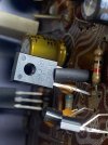
This transistor in the picture is the only transistor that I question. The one I removed (2sc1124) from position TR605 and TR606 on the other board are EBC Pinouts. The new KSC2690 transistors that I installed in their place are ECB pinout so I had to flip the 2 legs around and I shielded the middle leg. I have never had to do this on anything else that I have worked on so it was confusing to me. Every other plastic transistor that I changed was ECB and replaced with new ECB transistors and all facing the same direction as the originals.
 

Attachments

  • 24f67380-a282-4363-8cc5-63a494c5b8fb.jpg
    24f67380-a282-4363-8cc5-63a494c5b8fb.jpg
    64.2 KB · Views: 8
  • Like
Reactions: mbz
All the transistors in both boards are new except the 4 large silver metal transistors that I think are called OUTPUT trans.

Where did you get the new ones they are no longer available and if from e-bay most likely fake.
I triple checked all the PINOUTS several times on all the plastic transistors and I tested the Silver ones with a Multimeter. I used a Multimeter and tested the 2 left and 2 right silver round metal transistor and it said the two 2SB531's were bad so I installed new ones. It made no difference.

Once again I can dramatically lower the VR601 voltage by adjusting the VR602 Bias voltage, is this acceptable?

No, you need to set bias to .047 volts. 47mV's
This transistor in the picture is the only transistor that I question. The one I removed (2sc1124) from position TR605 and TR606 on the other board are EBC Pinouts. The new KSC2690 transistors that I installed in their place are ECB pinout so I had to flip the 2 legs around and I shielded the middle leg. I have never had to do this on anything else that I have worked on so it was confusing to me. Every other plastic transistor that I changed was ECB and replaced with new ECB transistors and all facing the same direction as the originals.
Was it bad? Maybe try putting it back in, But my money is on the output transistors, the TO-3 metal can transistors are bad or fake.

Athanasios
 
  • Like
Reactions: mbz
Once again I can dramatically lower the VR601 voltage by adjusting the VR602 Bias voltage, is this acceptable?
Irrelevent, possibly by lowering the bias you are "shutting down" one of the involved transistors.

DC Voltage at the left board OUT and E pins shows 25.4 Volts.
This is the issue. Expecting the jump from 6.xx volts previously since the right (shorting) channel is no longer dragging down the power supply.

#### try this first
Check orientation of TR601 and TR603, guessing you've used KSA992, pinout is ECB, important that the emitters of both transistors are connected to the same track

Otherwise continue
####

Please do the following,
Remove the 2 fuses from the right power amp board
Remove the 2 fuses from the left power amp board
Insert black MM probe into any black speaker post/connector
Measure resistance at left channel bottom fuse holder/clip for -B supply, black probe remains in black spkr post
Repeat for bottom fuse holder for +B supply

Have you had reason to remove the output transistors? If so did you carefully reassemble without damaging the mica insulators?

Remove Black probe from spkr post
Measure resistance across FR601, pix is not great, typically it's a white cement cylindrical resistor, may just be a plain 100ohm resistor, mounted raised above board, so one probe on each leg, see red in pix below.

Reinsert black probe into black spkr post

Reinstall the 2 fuses in the left power amp (only)

DBT power up
Measure to 1 decimal place, dc voltage at TR605e (or R617) Blue
Also measure Vdc other side of R617 yellow
Also measure at ceramic cap leg marked green

All voltages to 1 decimal place
 

Attachments

  • CA600amp_2.jpg
    CA600amp_2.jpg
    110.9 KB · Views: 12
Nashou66 - The TO-3 metal can came from MOUSER. I threw out all the old plastic transistors that I removed but not the 2 TO-3's cans. What I am understanding here is I need to set Bias before mid point voltage or is it visa versa?

MBZ - Yes I used KSA992 transistors in place of TR 601 and 603. The Transistors that came out were 2SA763's and they are ECB also, so the new trans face the same direction as the old ones, unless someone had already replaced the old ones and got it wrong. Ironically the Service Manual does not list 2SA763's as being in the Main Amp Boards???

I will do the other things you mention and report.
 
Last edited:
Nashou66 - The TO-3 metal can came from MOUSER. I threw out all the old plastic transistors that I removed but not the 2 TO-3's cans. What I am understanding here is I need to set Bias before mid point voltage or is it visa versa?
What transistors did you get from Mouser for the TO-3 cans?

Nashou
 
What transistors did you get from Mouser for the TO-3 cans?

Nashou
Got New from Mouser the MJ15016 to replace the 2SB531 transistors.

I have all my notes and I need to go back and see where I got my transistor replacement info from.

But once again I still have the old 2SB531's that I can put back in.
 
Last edited:
Got New from Mouser the MJ15016 to replace the 2SB531 transistors.

I have all my notes and I need to go back and see where I got my transistor replacement info from.

But once again I still have the old 2SB531's that I can put back in.
Did you change out the 2SD371's that are complimentary to the 2SB531's with the modern replacement that is the complementary to the MJ15016? Usually they need to be swapped out with their proper complimentary.

Athanasios
 
Back
Top Bottom