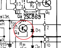
Hey guys, I've got a basket-case SX-1080 here that won't come out of protection, and I've already rebuilt the power supply and the protection board with no change at all to the symptom.
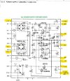
All supply voltages are good or within a few volts of what is listed in the schematic. I've replaced all electrolytics, transistors, and the rectifier diodes. Unfortunately, this supply had been cracked in the corner and was repaired at some point / traces bridged. I confirmed this was not an issue, and I even re-did the connections. Entire board had been removed (yeah, THAt sucked) and cleaned thoroughly so I could really inspect the solder joints. All joints have been reflowed.

This is where I'm wondering if I have a problem with Q3 (IC). All highlighted voltages check out fine except in the IC, and once again, completely rebuilt, new capacitors, new diodes, board removed and cleaned and touched up joints.
The issue I have now vs. the issue when I first got this in has not changed, so nothing I replaced caused any additional problem. I even removed the protection relay, pulled the cover off, cleaned the contacts with some paper soaked in deoxit, and threw 48v across it to confirm it engages on its own, so if I'm correct, this means the relay itself is fine.
I've been hesitant to start pulling the amplifier boards because they're all wired direct, just like the power supply and protection boards, and if I'm seeing funky voltages in that chip, I'm kind of focusing around that. But this is where I need some guidance if I'm looking in the right place...
I also tested the preamp section originally and that works fine. Any takers??
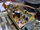
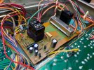
All supply voltages are good or within a few volts of what is listed in the schematic. I've replaced all electrolytics, transistors, and the rectifier diodes. Unfortunately, this supply had been cracked in the corner and was repaired at some point / traces bridged. I confirmed this was not an issue, and I even re-did the connections. Entire board had been removed (yeah, THAt sucked) and cleaned thoroughly so I could really inspect the solder joints. All joints have been reflowed.
This is where I'm wondering if I have a problem with Q3 (IC). All highlighted voltages check out fine except in the IC, and once again, completely rebuilt, new capacitors, new diodes, board removed and cleaned and touched up joints.
The issue I have now vs. the issue when I first got this in has not changed, so nothing I replaced caused any additional problem. I even removed the protection relay, pulled the cover off, cleaned the contacts with some paper soaked in deoxit, and threw 48v across it to confirm it engages on its own, so if I'm correct, this means the relay itself is fine.
I've been hesitant to start pulling the amplifier boards because they're all wired direct, just like the power supply and protection boards, and if I'm seeing funky voltages in that chip, I'm kind of focusing around that. But this is where I need some guidance if I'm looking in the right place...
I also tested the preamp section originally and that works fine. Any takers??