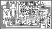
Doesn't really matter.What I am understanding here is I need to set Bias before mid point voltage or is it visa versa?


Doesn't really matter.What I am understanding here is I need to set Bias before mid point voltage or is it visa versa?
Are you sure, because in my 12th message I said, I can manipulate VR601 by Changing VR602Doesn't really matter.

Never take ohm reading with power on.MBZ - In regards to your requests. Check orientation of TR601 and TR603 YES, both Emitters are touching on the same track, so they are installed correct.
Resistance at both fuse bottom clips with no fuses in. I am guessing the amp needs to be ON the DBT and ON. Both readings start low them stabilize at about 5.40 ohms.
I 100% did not damage the mica insulators. I removed these transistor only to test them with a MM.
Resistance of FR601 - Starts low and goes up, stabilizes at about 17.5 ohms. If I reverse the MM probes it goes to OL. This is in the board and not desoldered.
Measure to One Decimal Place. Now sure what that means and my MM does not have a setting for that but I have other MM's.
VDC at TR605 Blue = 7.6
VDC at R617 Yellow = 9.17
VDC at Ceramic Cap = 21.0
There is another issue then.I can manipulate VR601 by Changing VR602
Redid with the power off and got the same 5.3 to 5.4 ohm readings at the bottom of the fuse holders.Never take ohm reading with power on.
There is another issue then.
Yamaha service manual adjusts the DC offset(mid-point) prior to adjusting the idle current(bias). If DC offset adjustment is available.
Is your multimeter reliable?Redid with the power off and got the same 5.3 to 5.4 ohm readings at the bottom of the fuse holders.
Do you mean the fusible resistor FR601, should be 100ohms though schematic errors do occur, the value will be printed on the body.Redid the ceramic resistor with the power off and got 17.5 ohm then I reversed the probes and got 11.1 ohms.
This was about getting TR605 b/c/e voltagesVDC at TR605 Blue = 7.6
VDC at R617 Yellow = 9.17
VDC at Ceramic Cap = 21.0
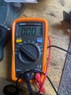
Not Sure. I will use a different one, see pics.Is your multimeter reliable?
Can't find a solder bridge anywhere and MICA's in good shape in tack. -B is 5.7 +B is 5.2 See attached pics.I can't see 5ohms for that measurement unless solder bridge or mica or...
plz remove the left channel outputs TR613, TR615 and redo measurements ie, black probe to blk spkr connector, red probe to bottom of -B fuse holder, repeat for bottom of +B fuse holder, amp powered off.
Redid with speaker selector set to off.Does setting the speaker selector to off have any effect, no speakers connected.
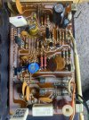
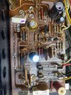
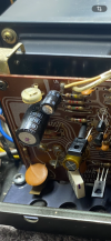
It is directly below the black capacitor in pictures. Labeled FR601 in schematic. Mine appears to be a resistor with color rings around it. I sent a better pic. Whitish one is Left Side and Greenish one is Right side board.Do you mean the fusible resistor FR601, should be 100ohms though schematic errors do occur, the value will be printed on the body.
Redid TR605 with Power and DBT on. E = .75 C = .77 B = 1.43This was about getting TR605 b/c/e voltages
B= 9.17V
C= 12.0V
E= 7.6V
Reinstalled TR 613 and 615. Amp On and DBT On, Red Probe on R617 (yellow in your pic) Started out at about 0.06 VCD and slowly went down to .000Base and emitter should be -ve values, assumed overlooked.
Possibly TR605 is off since Ve (-7.6V) > Vb(-9.17V)
Left channel outputs need to be reinstalled for this...
Can you clip the red probe to yellow (R617) then with black probe measure voltage at TR605e (blue), amp needs to be powered on with DBT, note sign, expect about +0.6Vdc
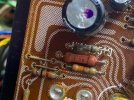
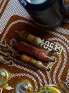
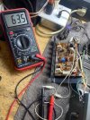
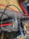
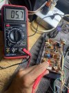
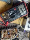
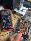
MBZ - this is why I didn't want to touch the Offset and Bias, because I am not 100% sure of what I am doing. The other MM, I was using earlier had Auto Settings so I could not read anything except what it was displaying.You understand that the dial/selector in the middle of your MM is used to select the function and also the range for measurements. All pix shown show the meter set on the 200k range, so when you see 5.7 it's actually 5.7k (5700) ohms not 5.7ohms. The meter also displays the kohm symbol slightly above the "5" as a reminder.
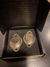
I make the suggestion in the post above. Google Ai is not always right. that chart I use is pretty good.Nashou66, this is the chart that I used to order the two metal can transistors MJ15016 to replace the 2SB531 and I am still not sure if they interchange and I have asked 3 times without and answer. Google AI says it is not a good replacement.
I want to replace Metal Can Transistors 2SD371 but that is not on list you provided.
I don't care of my Mouser bill gets to $100.00 just tell me what I may need?
2SD371 is not on the list? Do you have a suggestions for replacing these?I make the suggestion in the post above. Google Ai is not always right. that chart I use is pretty good.
And those MJ parts are what most use.
Athanasios
2SD371 is not on the list? Do you have a suggestions for replacing these?
this will help you pick the correct replacement transistors as long as they are still in production.
As ones that are coming to end of life I try to find suitable replacement and update the list .
Use the MJ21193G instead and its complimentary for the 2SD371's the MJ21194G
Athanasios
Crossing the legs is no big deal. Find the transistor that best matches the original and cross legs if necessaryso I don't have to cross the Collector and Base legs??? No one has told me if I did that right or not???