Blue Shadow
Waiting for Vintage Gear from this century
Reviving long dormant tube power amps-finally they work
I have a pair of Lux MB-3045s that have been well cared for since about 1988 when they were last used. I have gotten the parts to effect the change from using the NLA 8045G power tube and will be rewiring the amps to run KT88s in UL mode.
Previously, (years ago) one amp flashed the 12AX7 tube, the other did not. I swapped tubes to verify and well the flash on start up stayed with the amp. I have since tested those? two tubes and they are shorted. So a little care is needed bringing these amps back. Additionally, the last time I used these amps, one could be DC balanced and biased and one could not so I stopped using them. I should have sourced tubes and bought a box of them.
I have ordered the 4x22µF/315V replacement caps for a board as one amp has chalky looking ends on these caps. I will replace them with 22µF/450V caps.
I have checked the remaining components under the chassis, resistors and capacitors, to verify their values. I did this in circuit and a few are not what is specified, but I expected this. On both amps most of the out-of-spec results are identical and the labels on the devices are correct per the OM.
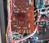
One amp, and I don't know which (flashing 12AX7 or not), has an over heated section of circuit board above a couple 67KΩ-2W resistors and I am replacing all four even though three measure correct. The fourth measured 100kΩ and it was on the over heated amp.
The only other differences are a 1µF cap reading 0.84, a 0.047 cap reading 0.20 and a 4700 resistor reading 4000Ω. All of these are on the same amp with the bad 2W resistor.
Now smart money says to replace these three components, so I'll do that.
My questions are:
Since both amps have readings on the components that were the same in circuit do I need to evaluate these units out-of-circuit?
When I first power these units up with a poor man's variac, should I do it without tubes? Can the procedure be offered such as time at different bulb levels and when to put tubes in?
One final question, the information I have specifies test voltages at TP1-TP6 and here is the easy question, this voltage references to ground, right? And I can get this anywhere from the input ground to the speaker common per the schematic?
Let me know if you need pics, schematics or the x-ray view of the board with component layout.
Thanks in advance.
Last edited: