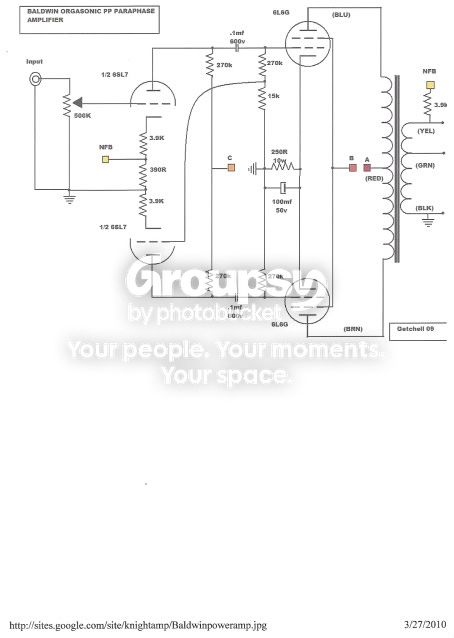
Uh huh. Scuzzer's test on his own unit shows why C4 was originally so big -- to keep the original circuit with the original OPT transformer stable. Removing it made the unit "take off" as previously discussed.
Installing a different output transformer in an otherwise established design was the subject of many electronic articles all through out the 50's, because so often folks would try to build a circuit with what they had on hand. All too often, the results produced the very kind of problems experienced here. No two OPTs are the same, even with similar specs, and even two of the same model will not display the exact same HF characteristics -- although they are close enough for mass production of high fidelity equipment.
Stabilizing a feedback amplifier is very much a hands on procedure, but here is a rather simple procedure I would suggest for Cricket's amp. It works very well for most two stage amplifiers using paraphase inverters, so that Batt could use it with his Baldwin amps, and Scuzzer with own Magnavox if he makes different mods to his:
1. Start with the original feedback resistor and capacitor values in place, connected to the original OPT tap, with C4 removed (this is only to start from square one so to speak, but can be further altered as will be seen). Then, install a temporary 250K pot at the input grid of the 6SL7. Using only two terminals of the pot (slider and one outside connection), wire it in series with the grid terminal -- that is, between the terminal, and the original wiring connected to it. Leave the temporary control turned for zero resistance for now, and if there is any input gain control provided, it should be turned up full.
2. With the amp properly loaded and a scope connected to the output, apply a 10 kHz square wave to the input, at such level as necessary to obtain 1 watt output, and check that the amp is remaining stable without any value of C4 in place.
3. If it is, adjust the value of the feedback cap so that any spike the leading edge of the wave may have is brought down to the top of the wave. Make sure you are looking at the leading edge here, and not a higher spike that might appear shortly after the leading edge.
4. If the amp will not remain stable without some value of C4 installed, install the smallest value of C4 necessary to make the amplifier remain stable. Then proceed with the rest of point #3 above.
5. Finally, adjust the temporary pot so that the top of the wave smooths out. When correctly set, the sides of the wave will remain straight, but likely tilt in ever so slightly, and the leading edge will usually form a small hump at the top of the wave before coming down and returning to the top of the wave and then smoothing out. This is a very good waveform to achieve, representing what is known as "critical stability".
6. Measure the value of the pot, and then install the closest value of series resistor permanently in its place. Do not be surprised if the value of the resistor is as high as say 100K. It usually falls within the range of 15-100K.
If desired, response tests with sine waves can then be run, where you will likely find the amplifier certainly flat throughout the audio bandwidth (20-20), and usually extending at least up to 30 kHz before smoothly dropping off. Values can be tweaked if needed to achieve the best response versus square wave presentation. Also, basic stability tests can now be run as well to determine the level of stability. If it will remain stable with any value of cap connected across the load resistor, that is a great start. Then see how big a cap it can handle without the load resistor connected. If it can handle up to .05 mfd for example with no other load connected, then the amplifier is solidly stable. The very best designs will remain stable with any value of cap-only load connected, while still maintaining the best of all the other performance attributes. The best performance from a design is always achieved when a balance of all performance parameters is met, rather than any one parameter optimized at the expense of the others.
The beauty of the this method (besides it's relative simplicity), is that with any kind of decent output transformer, a "C4" is usually not required, and adjustment can be made with the variable resistor once the basic FB cap is set. Without (or with only) a minimal C4, 20 kHz THD is kept very low with this method.
I don't know what values of feedback resistors Scuz and Mark actually ended up with, but as I recall, they were tossing around sensitivity values like .28 vac to drive the amp to full power without any feedback, and 1.44 vac with feedback. If that is the case, this represents about a 5X reduction, for 14 db of feedback. This is a healthy level of FB, in that it is not so excessive as to make for a major stabilization exercise, but is enough feedback to lower output impedance, flatten response, and lower distortion as well -- all very desirable things. If you'd like to keep the value of FB resistors in place that you ended up with earlier, you can do that, and then follow the same stabilization proceedure above.
This approach works because it uses the basic input capacitance and the Miller effect taking place in the input triode to work in conjunction with the new input resistor to form a low pass network filter that controls HF response. As you know Keg -- that will of course make it much harder to model. But if your program has such data available, you could plug in the final resistor value chosen to determine the actual LP filter performance.
As for the inverter itself, I would recommend converting it to a floating paraphase type, as not only is the amplitude balance between the two outputs maintained much better, but the phase is as well over a broad frequency range. In the floating version, the bottom section actually has a significant amount of feedback around it, helping to correct these matters. It really is a significant improvement over the basic paraphase design originally in place.
Finally, as for the UL taps, all you can do is try them. If they are the all too typical "40%" taps that virtually all current transformer manufacturers offer on their transformers, it is not the best positioning for 6V6 class tubes. These tubes operate well in UL with about a 25% tapping point, and beyond that, power output starts to suffer, so all you can do is try it and see.
With the OPT transformer upgrade, power supply upgrade (regulated screens), inverter upgrade (to floating style), and stable NFB installed, Mark's amp will set a performance level others will have to work very hard at to exceed!
Dave