• The move to the new server is done. There are some software and database maintenance updates in process. This has us passing the hat around to help out. We appreciate any donations. Seriously, even a dollar helps. The payment page may be found here - https://www.audiokarma.org/support.html

Dipole turnstile FM antenna question

Zolton

Well-Known Member
I'm planning on installing a home made antenna in my attic and supplying 4 stereo set-ups with it. I did some research a while back and found a half wave folded dipole turnstile design. Basically 2 half wave folded dipoles wired in parallel and mounted in an X pattern to catch signals from north/south and east/west. Since this will take up some valuable head room in my attic, I was wondering if instead of mounting the two parts in an X pattern, if it would work just as well to mount the one section in the north/south orientation on the end wall and the east/west section along the peak about 2 feet higher, with the pieces in more of a T pattern instead of the X. The two sections would still be perpendicular to one another, they just wouldn't overlap in the middle. Problems with this set-up?
 
Register to hide this ad
I don't see any major problems.
Not sure if you would create phasing problems-the same signal with a very slight time-difference between them (not multi-path).
I've used 2 of the cheapy wire t's like that-no problems. I've also used 2 cheapy t's with a knife switch to switch E-W or N-S.
If your gonna have a long run of cable, you may want to consider an in-line amp.
Let us know how it goes.
 
A turnstile isn't a good antenna for line of sight reception. They have a high angle of radiation and low gain at low angles. If you arranged them in a T instead of an X then the radiation plot is distorted making it even worse. Your best bet is to hang two dipoles and feed them independently. At a height of 20 feet you will get approx. 5db of gain to the broad side. You could also try a cheap ground plane and hang it from a rafter. I'd try 28 inches for the length. http://www.hamuniverse.com/2metergp.html
 
If I remember correctly as long as you have them at equal wavelengths of distance apart from one another there shouldn't be any phase errors causing multipath and other odd issues.
In reality it probably doesn't matter where you place the antennas. I have found with FM broadcast reception that even when in theory things should work sometimes they don't and oddly enough other times when something shouldn't work at all it has been known to work magic in antenna placement/design.
Tried and true comes to mind. Hook them up to your receiver and place them in random places, walk around with the antenna and find the sweet spots while listening. For FM reception this seems to be more important than actually going by theory ;)
 
Hacker. From what I've read, if I connect the two dipoles together with a 22 inch length of coax it should take care of the phasing issue.

The stations I like in my area are 107.1, 107.5 and 107.9. The mid way of the three being 107.5. If I make the length of each 1/2 wave folded dipole 49.5 inches long, it should be tuned into this frequency section nicely. Connect a balun to the leads from one half and head off with a coax to the required areas, splitting it when required. Then a balancing transformer at each end connected to the receiver's 300 ohm antenna terminals.

I have a fair size home and 4 systems I'd like to run this feed to. And I like to have them on all at the same time on the same station (vintage surround sound :smoke:). Will there be excessive signal losses if I do this?
 
ngOK. The reason I was going with the turnstile is because the three stations worth listening to in the area are situated to the: a) west, b) south, c) east. As such, an antenna that is directional isn't preferable. I'm looking at your ground plane suggestion. Is the 28 inches per element? If so, the only location I could mount it in my attic is right against a large brick chimney. Probably not the best spot. I've heard of a J-pole too. These are quite lengthy and I'd have to mount it on the outside of the house. The roof peak is about 40 feet high and we are on a hill so that would be ideal. However, I don't think the wife would be keen on an exterior antenna (nice century home and all). :nono:

I might have to install one while she's away for the weekend and hope for the best. :D
 
I'm planning on installing a home made antenna in my attic and supplying 4 stereo set-ups with it. I did some research a while back and found a half wave folded dipole turnstile design. Basically 2 half wave folded dipoles wired in parallel and mounted in an X pattern to catch signals from north/south and east/west. Since this will take up some valuable head room in my attic, I was wondering if instead of mounting the two parts in an X pattern, if it would work just as well to mount the one section in the north/south orientation on the end wall and the east/west section along the peak about 2 feet higher, with the pieces in more of a T pattern instead of the X. The two sections would still be perpendicular to one another, they just wouldn't overlap in the middle. Problems with this set-up?

Use a dipole and mount it vertical - it will receive in a 360 pattern equally. Like this
http://fmdxantenna.com/proddetail.php?prod=FMDipUS
If you want 300 ohm output, use a single folded dipole vertically.
This assumes you have 5-6 feet to work with from attic bottom to the roof peak.
The turnstile design with two dipoles connected together is not a great design
If you want to know why, there is a long thread about that design starting here -
http://tech.groups.yahoo.com/group/FMtuners/message/31188

In a nutshell, it has -3dB gain compared to a single dipole, and very poor response curves away from the design frequency. The correct phasing harness is critical.
 
Last edited:
ngOK. The reason I was going with the turnstile is because the three stations worth listening to in the area are situated to the: a) west, b) south, c) east. As such, an antenna that is directional isn't preferable. I'm looking at your ground plane suggestion. Is the 28 inches per element? If so, the only location I could mount it in my attic is right against a large brick chimney. Probably not the best spot. I've heard of a J-pole too. These are quite lengthy and I'd have to mount it on the outside of the house. The roof peak is about 40 feet high and we are on a hill so that would be ideal. However, I don't think the wife would be keen on an exterior antenna (nice century home and all). :nono:

I might have to install one while she's away for the weekend and hope for the best. :D

28" is 1/4 wave at 100mhz which will provide a reasonable SWR from 88 - 107mhz. All elements can be the same length. It's a receiving application so exact measurements aren't important with this type of antenna. Try hanging it from a rafter in the attic and see how it does.

A dipole oriented vertically is a good idea too. Make sure the feedline goes out horizontal 3 or 4 feet.

A jpole is ok too but no gain over a vertical gp. But you could buld a jpole from 300ohm twinlead very easily. Shove it in a length of PVC pipe and mount it on a vent pipe on the roof. Paint it black. Google twinlead jpole and go at it.

I'm a ham radio operator and I've built most of my own antennas. It's fun to try different designs.
 
28" is 1/4 wave at 100mhz which will provide a reasonable SWR from 88 - 107mhz. All elements can be the same length. It's a receiving application so exact measurements aren't important with this type of antenna. Try hanging it from a rafter in the attic and see how it does.

A dipole oriented vertically is a good idea too. Make sure the feedline goes out horizontal 3 or 4 feet.

A jpole is ok too but no gain over a vertical gp. But you could buld a jpole from 300ohm twinlead very easily. Shove it in a length of PVC pipe and mount it on a vent pipe on the roof. Paint it black. Google twinlead jpole and go at it.

I'm a ham radio operator and I've built most of my own antennas. It's fun to try different designs.

Regarding the GP...the diagram in your link showed a triangular shaped doo-dad. Was each arm of the doo-dad 28 inches or the height of the entire doo-dad 28 inches?
 
Each element is 28". The formula for the elements = 234 / Mhz * 12". EX) For Omaha's Z92 @ 92.3Mhz you plug 234 / 92.3 * 12 = 30.4" . The antenna will work across the FM dial so 28" is in the middle.

For this antenna the feedpoint impedance is 50 ohms but a 75ohm cable will work fine. You will need to install a PL-259 to the coax cable or find a converter that directly converts F to SO-239 or PL-259. Like #3111 here at Universal radio. http://www.rffun.com/catalog/parts/f.html

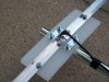
You can make your connector that would work with F connectors too. Here are various examples of feeds I used for some of my homemade transmitting antennas. The first one doesn't use a connector at all. I soldered electrical connectors to the coax and directly fed the radiators. The second one uses a SO239 mounted to some scrape alum and fed against 24 radials buried in the lawn. The 3rd is a ground plane with two 17 foot radials and a 17 foot vertical element.
 

Attachments

  • 100_0640.jpg
    100_0640.jpg
    100.7 KB · Views: 37
  • IMG_0423.jpg
    IMG_0423.jpg
    60.7 KB · Views: 33
  • IMG_0426.jpg
    IMG_0426.jpg
    48.3 KB · Views: 40
ngOK. The reason I was going with the turnstile is because the three stations worth listening to in the area are situated to the: a) west, b) south, c) east. As such, an antenna that is directional isn't preferable. I'm looking at your ground plane suggestion. Is the 28 inches per element? If so, the only location I could mount it in my attic is right against a large brick chimney. Probably not the best spot. I've heard of a J-pole too. These are quite lengthy and I'd have to mount it on the outside of the house. The roof peak is about 40 feet high and we are on a hill so that would be ideal. However, I don't think the wife would be keen on an exterior antenna (nice century home and all). :nono:

I might have to install one while she's away for the weekend and hope for the best. :D

Sounds like you may have issues with a 5-6' vertical dipole. The other way to do it is to make two half wave dipoles, (single wire, inherently 75 ohm) mount at right angles, and attach 75 ohm coax to each center feed output. A current balun at each output would be a plus, but you may be OK without it.

Make one coax ouput line 1/4 wave longer than the other, i.e. longer by half the width of the half wave dipole. Feed these 2 outputs into a 2:1 75 ohm splitter, and take the feed from there. If you are splitting it up later into 4 feeds, I would try a 1 in 4 out TV distribution amp with an effective gain per output of 1 or 2 dB. These are usually cheap at places like Home Depot. Don't use 1 line and then split as you go to the next room, or the last line will be severely attenuated compared to the first feed.
 
Sounds like you may have issues with a 5-6' vertical dipole. The other way to do it is to make two half wave dipoles, (single wire, inherently 75 ohm) mount at right angles, and attach 75 ohm coax to each center feed output. A current balun at each output would be a plus, but you may be OK without it.

Make one coax ouput line 1/4 wave longer than the other, i.e. longer by half the width of the half wave dipole. Feed these 2 outputs into a 2:1 75 ohm splitter, and take the feed from there. If you are splitting it up later into 4 feeds, I would try a 1 in 4 out TV distribution amp with an effective gain per output of 1 or 2 dB. These are usually cheap at places like Home Depot. Don't use 1 line and then split as you go to the next room, or the last line will be severely attenuated compared to the first feed.

So you are saying to split it into 4 at the source and not as the coax travels through the house? ****...that changes my plans :sigh:
 
So you are saying to split it into 4 at the source and not as the coax travels through the house? ****...that changes my plans :sigh:

Right, each 1:2 splitter loses about 3.5. So after the first split, you are -3.5dB, after the 2nd -7dB, and after the third split -10.5dB. It may still work OK, but at least you have the info on what will happen in advance.
Switches are better than splitters, as they have no loss. I go direct from the roof to the first floor, into a 1 IN 3 out switch. From there the signal goes to 3 tuners, I only listen to 1 at a time.
 
Right, each 1:2 splitter loses about 3.5. So after the first split, you are -3.5dB, after the 2nd -7dB, and after the third split -10.5dB. It may still work OK, but at least you have the info on what will happen in advance.
Switches are better than splitters, as they have no loss. I go direct from the roof to the first floor, into a 1 IN 3 out switch. From there the signal goes to 3 tuners, I only listen to 1 at a time.

Ah...I was hoping to listen to all four at once (at least having all four on the same channel at once and being able to roam around the house and hear each one playing the same source). I'm doing that at the present as I have each receiver on their own antenna of some sort. Some are getting a strong signal and some not. The plan was to come up with a way of getting a nice strong signal to all four units using one source.
 
Yet another use for a FM transmitter. Sometimes if the station is distant, I'll re-broadcast it and only need a ribbon antenna or none at all to receive through out the house.
 
Ah...I was hoping to listen to all four at once (at least having all four on the same channel at once and being able to roam around the house and hear each one playing the same source). I'm doing that at the present as I have each receiver on their own antenna of some sort. Some are getting a strong signal and some not. The plan was to come up with a way of getting a nice strong signal to all four units using one source.

Well, the best way to get there (without an FM transmitter or wireless internet) is to bring the FM coax down to the most interior tuner, and then use a 1 in, 4 out amp/splitter described before, i.e. a hub and spoke topology. You may also decide the upstairs tuners are OK with dipoles, and you really only need to split it twice.

You can likely use only one dipole if you carefully map out the transmitter locations, and power, and then rotate the dipole to an optimal/compromise diagonal position that best picks up all stations.

A dipole has a figure 8 pattern, and the notch is quite narrow. You should lay out it using google earth and the exact coordinates for the transmitters and your home. You can get the transmitter coordinates from clicking on the i button to left of call letters here
http://www.radio-locator.com/
 
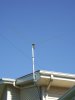
If you angle the legs of the dipole towards each other horizontally so that there is approximatly a 45 degree angle between them (horizontal V shape), then the nulls will be filled in. Instead of a figure 8 shape the pattern will be a peanut shape. This is how I orient my 6 meter transmitting dipole. I confirmed this is the case with antenna modelling software and in actual use. See the actual pic of mine.
 

Attachments

  • 100_0213.jpg
    100_0213.jpg
    35.2 KB · Views: 30
If you angle the legs of the dipole towards each other horizontally so that there is approximatly a 45 degree angle between them (horizontal V shape), then the nulls will be filled in. Instead of a figure 8 shape the pattern will be a peanut shape. This is how I orient my 6 meter transmitting dipole. I confirmed this is the case with antenna modelling software and in actual use. See the actual pic of mine.

I'm just trying to get some perspective on that photo. So that is two 3 meter solid elements mounted in a horizontal V pattern? Would that be a full wave dipole?
 
This is a 1/2 wave dipole antenna for the 6-meter ham radio band and I have it centered for 50.125mhz. It's a horizontal V. An FM broadcast band antenna would have each leg cut to around 30" give or take. In a receiving application it's not critical. It's facing west and the broadside gain east/west is 7.35dbi over real ground. It's gain to the north/south is approx -0.35dbi. The dot on the plot is near the -3db beamwidth and is 4.7dbi.
 

Attachments

  • 6mAnt.jpg
    6mAnt.jpg
    37.8 KB · Views: 9
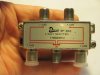
After receiving all this information (thanks guys), I think my first attempt will be to mount a 1/2 wave folded dipole vertically in my attic. I realize it's much better to put it outside but....the wife....you know.:nono: There is just enough room at the peak to hang it (about 52 inches). I'll hang it from an eye hook so it can swing out of the way when required (we store a lot of junk up there too), connect a balun at the stubs, a short run of coax to the 4 way splitter, then separate coaxes to each tuner. The coax I have on hand is Belden RG 62A/U (mil spec C-17). Is this decent stuff for this application? The splitter I have on hand may be a piece of shite...it's a Provo SP-4HO 4-way (5-1000MHz) and at each output is written 7.4dB. Does this mean 7.4dB signal loss at each one? That blows. :sigh:
It's probably for TV use. If it's crap for FM then what should I be using?
 

Attachments

  • IMG_1833.jpg
    IMG_1833.jpg
    63 KB · Views: 17
Back
Top Bottom